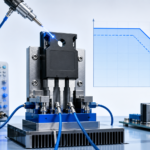
A series gate resistor is one of the simplest components in a power stage, yet it influences several competing outcomes at once. Increasing resistance generally slows the gate-current pulse, which can reduce switch-node ringing and high-frequency emissions. The same change also extends the voltage-current overlap interval and can raise switching loss. The useful value is therefore not the largest resistor that makes the waveform look quiet; it is the smallest value that produces repeatable switching with acceptable voltage stress, EMI, and temperature.
Define the behavior you are trying to change
Before changing resistance, identify the edge and the symptom. Turn-on resistance mainly affects the drain-voltage fall and current rise. Turn-off resistance affects the drain-voltage rise, current fall, and the margin against dynamic avalanche. A single resistor controls both edges, while a resistor-and-diode network can tune them independently. Separate control is valuable when the power stage needs a slower turn-on for EMI but a faster turn-off for short-circuit response.
The total resistance seen by the gate includes the driver output resistance, the external resistor, package resistance, and PCB trace resistance. The gate is also nonlinear: current changes while the device moves through the Miller plateau. This is why a calculation gives a starting range rather than a final value.
Build a practical starting point
Use the driver supply voltage, Miller-plateau voltage, driver source or sink capability, and gate-charge curve to estimate gate current. Then check that the driver can dissipate the resulting gate-drive power at the intended switching frequency. If the MOSFET is paralleled, give each device its own gate resistor so small threshold and loop differences do not create uncontrolled current sharing during transitions.
- Place the resistor close to the MOSFET gate so it damps the local gate loop.
- Keep the driver-to-source return short and separate from the high-current power path.
- Provide footprints for independent turn-on and turn-off resistors during prototype tuning.
- Use a Kelvin-source connection when the package provides one.
Tune with correlated measurements
Change one parameter at a time and capture gate-to-source voltage, drain-to-source voltage, and drain current with probes suited to the edge rate. Observe overshoot, ringing frequency, plateau behavior, false turn-on, and the switching-energy area. Repeat at minimum and maximum input voltage, representative current, and hot operating conditions. A resistor that works on an open bench at room temperature may not be adequate when the enclosure is hot and parasitic capacitances shift.
Do not use gate resistance to conceal a large commutation loop. If a small resistor change produces a dramatic overshoot change, first inspect placement of the input ceramic capacitors, driver bypass capacitor, and source return. Correcting the loop often restores efficiency while retaining low noise.
Use a release checklist
- Confirm peak drain voltage remains below the derated device limit.
- Confirm gate voltage stays inside both positive and negative absolute maximum ratings.
- Compare switching energy and case temperature across resistor options.
- Run conducted and radiated scans with the production enclosure and cable set.
- Record the selected resistance, operating point, probes, and waveform bandwidth.
The gate resistor should be treated as a documented calibration component. When its selection is tied to measured waveforms and thermal data, it becomes a predictable part of the switching design rather than a late-stage EMI patch.
Technical reference: Texas Instruments, EMI mitigation and gate-resistor trade-offs.