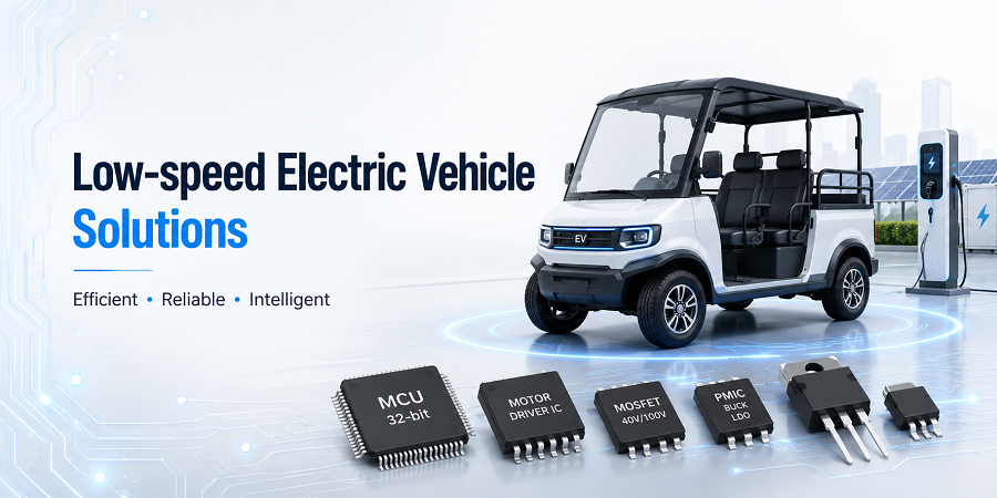
Efficient battery, auxiliary-power and traction-drive semiconductor solutions for electric scooters, mobility vehicles, golf carts, utility carts and other low-speed electric platforms.
Integrated battery and traction-drive architecture for low-speed electric mobility
Low-speed electric vehicles require efficient energy transfer from the traction battery to the motor while also supplying stable low-voltage rails for controllers, lighting, displays and communication modules. The solution combines a protected battery pack, a high-efficiency DC/DC converter, a three-phase BLDC/PMSM motor-driver stage and an MCU-based control-and-protection platform. Together these blocks support smooth torque delivery, regenerative operation, battery supervision, auxiliary-power conversion and dependable protection across changing load, road and environmental conditions.
Key advantages
High traction efficiency
Extended driving range
Smooth startup torque
Regenerative-braking support
Stable 12 V / 5 V auxiliary rails
Low conduction loss
Fast current-loop response
Battery-state supervision
Overcurrent and short-circuit protection
Undervoltage and overvoltage protection
Thermal derating support
Scalable vehicle power levels
Low-speed EV powertrain architecture and product mapping
Low-Speed Electric Vehicle Drive Architecture
Charge input, traction battery, auxiliary DC/DC conversion, a three-phase BLDC/PMSM motor driver, vehicle drivetrain and coordinated MCU protection.
Tip: Select a block in the diagram or choose a module from the list. On mobile, swipe horizontally to view the full diagram.
Explore the low-speed electric vehicle architecture through the interactive block diagram. Select the battery pack, DC/DC converter, BLDC/PMSM motor driver or MCU controller-and-protection block to review its design role, key engineering considerations and placeholder MOT device mapping.
About the solution
Coordinated traction, auxiliary-power and battery supervision for efficient electric mobility
The traction battery feeds a three-phase MOSFET bridge that controls the BLDC or PMSM motor, while a separate DC/DC converter supplies stable low-voltage rails for the vehicle controller, dashboard, lighting and communication electronics. The MCU coordinates torque commands, current regulation, regenerative braking, battery limits, thermal derating and fault shutdown so the vehicle can deliver predictable performance and safe operation throughout the available state-of-charge range.
Scalable for scooters, mobility vehicles, golf carts and compact utility platforms
The same architecture can be adapted for two-wheel and three-wheel electric vehicles, neighborhood mobility vehicles, golf carts, warehouse tugs, utility carts, campus transport and other low-speed platforms. Battery voltage, inverter current, motor type, regenerative-braking strategy, auxiliary-rail power and communication interfaces can be scaled to match vehicle mass, gradeability, range and environmental requirements.
Device categories aligned with the battery, conversion, motor-drive and protection paths
Battery-path MOSFETs and protection devices, buck and buck-boost converter switches, Schottky and fast-recovery diodes, three-phase inverter MOSFETs, high-current gate drivers, current- and voltage-sense devices, MCU and supervisor functions, CAN or LIN interfaces and auxiliary-power components provide a practical semiconductor platform for efficient and serviceable low-speed electric vehicles.
Coordinated traction, auxiliary-power and battery supervision for efficient electric mobility
The traction battery feeds a three-phase MOSFET bridge that controls the BLDC or PMSM motor, while a separate DC/DC converter supplies stable low-voltage rails for the vehicle controller, dashboard, lighting and communication electronics. The MCU coordinates torque commands, current regulation, regenerative braking, battery limits, thermal derating and fault shutdown so the vehicle can deliver predictable performance and safe operation throughout the available state-of-charge range.
Scalable for scooters, mobility vehicles, golf carts and compact utility platforms
The same architecture can be adapted for two-wheel and three-wheel electric vehicles, neighborhood mobility vehicles, golf carts, warehouse tugs, utility carts, campus transport and other low-speed platforms. Battery voltage, inverter current, motor type, regenerative-braking strategy, auxiliary-rail power and communication interfaces can be scaled to match vehicle mass, gradeability, range and environmental requirements.
Device categories aligned with the battery, conversion, motor-drive and protection paths
Battery-path MOSFETs and protection devices, buck and buck-boost converter switches, Schottky and fast-recovery diodes, three-phase inverter MOSFETs, high-current gate drivers, current- and voltage-sense devices, MCU and supervisor functions, CAN or LIN interfaces and auxiliary-power components provide a practical semiconductor platform for efficient and serviceable low-speed electric vehicles.
Contact our engineering team
Talk to Engineering Sales
Tell us your operating conditions and volume plan.
Share your target application, electrical requirements, package preference and estimated quantity. Our field application engineers will follow up with the right battery-charging devices and reference designs for your project.
Response from a dedicated FAE within 1 business day