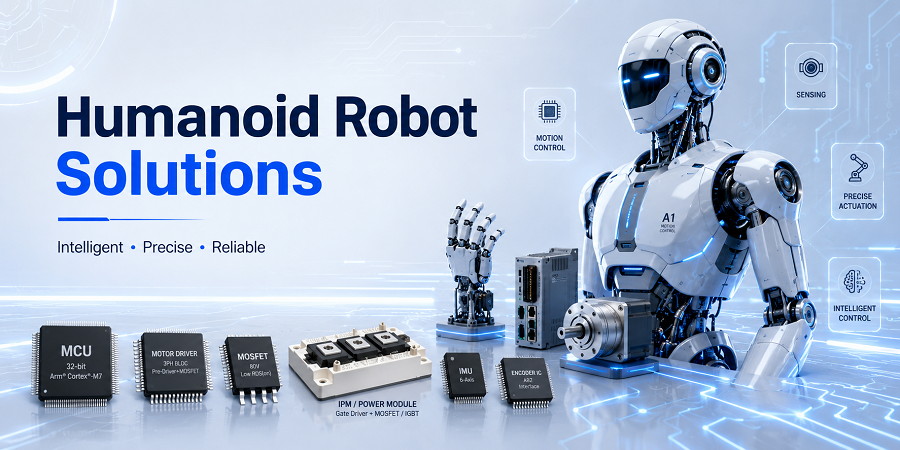
High-power-density MOSFET motor-drive solutions for compact humanoid joints that demand precise torque control, rapid response, regenerative operation and reliable thermal performance.
High-density joint actuation for precise and responsive humanoid motion
Humanoid robots distribute compact electric actuators across the legs, arms, waist, hands and head. Each joint drive converts the robot battery bus into accurately controlled three-phase current for a BLDC or PMSM motor while responding to torque, speed and position commands in real time. The Motor Drive MOSFET stage must combine low on-resistance, controlled gate charge, strong safe-operating-area margin, robust avalanche behavior and efficient thermal transfer so the actuator can deliver high peak torque, smooth low-speed motion, rapid direction changes and regenerative energy flow inside a tightly constrained mechanical package.
Key advantages
High joint power density
Low conduction loss
Fast PWM commutation
High peak-current capability
Precise torque response
Regenerative energy handling
Low thermal rise
Compact actuator integration
Controlled switching EMI
Rapid fault shutdown
Wide battery-bus compatibility
Scalable multi-joint architecture
Humanoid joint drive and product mapping
Distributed Humanoid Joint Actuator Architecture
Battery-bus conversion, six-switch three-phase inversion, compact joint motor actuation, regenerative current flow and coordinated current, position and temperature feedback.
Tip: Select the filled MOSFET power-stage block in the diagram or choose it from the list. On mobile, swipe horizontally to view the full diagram.
Explore the humanoid joint-drive architecture through an interactive image map. Select the Motor Drive MOSFET stage to review its electrical role, key selection criteria and placeholder MOT product mapping.
About the solution
Compact three-phase inversion for high-torque humanoid joint actuators
A humanoid joint actuator typically combines a motor, reduction mechanism, position sensing and a tightly integrated three-phase inverter. Six Motor Drive MOSFETs form the high-side and low-side phase switches that regulate current and torque through high-frequency PWM. Low conduction loss, predictable switching behavior, controlled dead time and robust handling of inductive and regenerative current help the joint deliver smooth motion, rapid acceleration and safe deceleration without exceeding the actuator’s thermal limits.
Reusable across legs, arms, waist, hands, neck and mobile-base actuators
The same inverter building block can be scaled across a humanoid robot’s distributed motion system. High-torque hip and knee joints may prioritize peak-current and thermal capability, while arms, wrists, fingers and head mechanisms may prioritize compact packages, high switching frequency and low acoustic noise. Voltage rating, current capability, package size, cooling method and parallel-device count can be adapted to each actuator’s torque, speed, duty cycle and mechanical envelope.
Low-voltage and medium-voltage MOSFET options for compact, efficient joint drives
N-channel power MOSFETs with low RDS(on), optimized gate charge, controlled reverse-recovery behavior, strong avalanche capability and thermally efficient packages provide a practical foundation for humanoid motor drives. Device selection can be optimized for battery-bus voltage, switching frequency, peak phase current, regenerative energy, PCB area and cooling constraints while maintaining the safety margin required for repeated dynamic motion.
Compact three-phase inversion for high-torque humanoid joint actuators
A humanoid joint actuator typically combines a motor, reduction mechanism, position sensing and a tightly integrated three-phase inverter. Six Motor Drive MOSFETs form the high-side and low-side phase switches that regulate current and torque through high-frequency PWM. Low conduction loss, predictable switching behavior, controlled dead time and robust handling of inductive and regenerative current help the joint deliver smooth motion, rapid acceleration and safe deceleration without exceeding the actuator’s thermal limits.
Reusable across legs, arms, waist, hands, neck and mobile-base actuators
The same inverter building block can be scaled across a humanoid robot’s distributed motion system. High-torque hip and knee joints may prioritize peak-current and thermal capability, while arms, wrists, fingers and head mechanisms may prioritize compact packages, high switching frequency and low acoustic noise. Voltage rating, current capability, package size, cooling method and parallel-device count can be adapted to each actuator’s torque, speed, duty cycle and mechanical envelope.
Low-voltage and medium-voltage MOSFET options for compact, efficient joint drives
N-channel power MOSFETs with low RDS(on), optimized gate charge, controlled reverse-recovery behavior, strong avalanche capability and thermally efficient packages provide a practical foundation for humanoid motor drives. Device selection can be optimized for battery-bus voltage, switching frequency, peak phase current, regenerative energy, PCB area and cooling constraints while maintaining the safety margin required for repeated dynamic motion.
Contact our engineering team
Talk to Engineering Sales
Tell us your operating conditions and volume plan.
Share your target application, electrical requirements, package preference and estimated quantity. Our field application engineers will follow up with the right battery-charging devices and reference designs for your project.
Response from a dedicated FAE within 1 business day