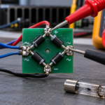
A Schottky rectifier is often selected for its low forward drop and fast switching behavior. Those benefits can obscure a different loss mechanism: reverse leakage. Leakage rises with reverse voltage and can increase sharply with junction temperature. In a poorly cooled design, leakage power heats the junction, which causes more leakage and more heating. If heat removal cannot balance that feedback, the operating point becomes unstable.
Use the correct loss model
Forward conduction loss is approximately related to forward voltage, current, and conduction duty cycle. Reverse loss depends on reverse voltage, leakage current, and blocking duty cycle. The room-temperature typical leakage value is rarely sufficient for a worst-case design. Use maximum or appropriately derated data at the expected reverse voltage and high junction temperature.
In a converter, include waveform shape rather than assuming a constant voltage. Ringing and overshoot can move the diode into a region with significantly higher leakage. In a battery-protection or ORing function, the blocking interval may be long enough for reverse loss to dominate the average temperature.
Close the electrothermal calculation
A first-pass analysis can iterate between electrical loss and temperature:
- Assume an initial junction temperature.
- Estimate forward and reverse losses at that temperature.
- Use the board and package thermal resistance to calculate a new junction temperature.
- Repeat until the result converges or clearly diverges.
A stable result should retain margin for leakage variation, ambient tolerance, copper manufacturing variation, airflow blockage, and heat from neighboring components. A calculation that converges only near the maximum junction rating is not a robust design.
Compare technologies at the system level
A lower forward drop does not guarantee lower total loss. A silicon PN rectifier may have higher conduction loss but much lower reverse leakage. A MOSFET-based ideal-diode circuit can reduce forward loss at higher current, although it adds control complexity and must handle reverse battery and transient conditions. Compare the complete operating profile rather than a single datasheet number.
- Maximum continuous and surge current
- Reverse voltage including transients
- Forward duty cycle and blocking duty cycle
- Maximum ambient and nearby heat sources
- Available copper area, vias, and airflow
- Failure response if leakage rises unexpectedly
Validate the hottest credible state
Test the production PCB at maximum reverse voltage and worst thermal conditions. Stabilize the assembly long enough to observe whether current and temperature settle. Measure leakage supply current and board temperature while estimating junction temperature from a characterized thermal path. Repeat with hot-start conditions because an already-warm diode can move quickly toward an unstable point.
Also test dynamic transitions. Inrush current into downstream capacitance, reverse-recovery interaction with other devices, and voltage overshoot may stress the diode beyond the steady-state analysis. The release decision should cover both electrothermal stability and transient ratings.
Schottky rectifiers remain an excellent choice when their low forward loss is matched to the voltage and temperature envelope. The essential step is to treat reverse leakage as a temperature-dependent power term, not as a negligible line in the datasheet.
Technical reference: Nexperia, reverse-battery protection and Schottky leakage behavior.