Application of core parameters in robotic joint drive
The core structure of robotic joints is a three-phase reverse transformation (6 MOSFETs consisting of 3 upper and 3 lower), driving BLDC/PMSM electrics, typical of the following: power voltage 24 ~ 48 V (industrial robotic joints), rated current 20 ~ 80 A (based on the size of the joint load), PWM frequency 10 ~ 50 kHz (complex finely adjusted speed), high frequency start-up (tens of times per second), transient blackout (two ~3 times the nominal current) and internal space compaction (hard heat spread, ambient temperature 60 ~ 100°C).

1. Pressure parameters (V = 150 V, V = ± 20 V): Fit for high-pressure conditions, secure sufficiency
The most commonly used electric voltage for robotic joints is 24V, 36V, 48V (heavy joints up to 60V), the maximum voltage for the MOSFETs is the peak of the parent-line voltage (e. g. 48V parent line, peak of about 67V), the peak voltage at the time of the break (approximately 15-25V), and the actual maximum voltage of 92V. The MOT7130T4 V = 150V (minimal value) saves more than 63% of the actual maximum working voltage in safety sufficient to effectively suppress the risk of a perusal peak blow-off and avoid the failure of the device due to overpressure.
2. Current parameters (I = 263A, I = 1052A): Loading large currents in response to transient shocks
Mechanical joint-driven current demand changes with load: current 10-20A on light load (e. g. small joint rotation), current 40~80A on full load (e. g. joint lift load), current instantaneous current 150~250A on block (e. g. joint-barrel delay)
More critically, its I = 1052A (short-time pulse current), transient large currents (150~250A), which can easily withstand a joint blockage (150~250A), combined with specifications Figure11 (maximum safe workspace curve), which, at 10 m ~100 ms pulse width, meets the requirements of a joint transient condition; and, at the same time, continuous flow of a bipolar tube I = 263A, pulse current I = 1052A, which corresponds to a continuous flow requirement in a three-phase full-bridge bridge, without the need for additional serial reductive diodes to simplify electrical design.
3. Conveyment properties (R≤3. 8 m): Reduced transport losses and decomposition of dispersive heat pressure
The robotic joint drive is a continuous operation of large currents, the loss is dominated by a direct loss (over 70 per cent), and the factor used to calculate the direct loss is P=I2R, the smaller the loss is the lower. MOT7130T4 In V = 10V, I = 40A, R's typical value is only 3 m, with a maximum value of 3. 8 m (Specific Book “ELECTRIC CHARACTERISTICS”), which is much better than the same high voltage current MOSFETs.
Switch feature (Q = 125nC, Quick Switch Time): Fit to high frequency PWM, increase speed accuracy
The Q = 125nC (typical value) of MOT7130T4 and the Miller Charge (Q) is only 32nC (share 25. 6 per cent) which can effectively reduce the time of the Miller platform during switching and reduce the loss of the switch (37. 5 per cent less than the Q = 200nC equivalent); its switch time parameters are suitable for high frequency scenarios: t= 32ns, t= 60ns, t= 48ns, which can accurately respond to high frequency PWM signals and avoid motor rate fluctuations and twirling deviations due to switch delays.
In addition, its reverse transfer cap C = 26pF, the smaller the reverse transfer of the cape, the smaller the coupling interference between the fence sources, can reduce the distortion of PWM signals and increase the speed accuracy, while reducing electromagnetic interference (EMC), avoiding interference with joint-driven controlled circuits (e. g. , MMU, encoder feedback circuits) and adapting to the precision control requirements of robotic joints.
Temperature and dissipation properties (T=150°C, R=0. 28°C/W): appliance with bad dissipation to ensure long-term reliability
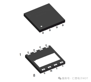
The inner space of robotic joints is extremely compact, and the MOSFETs is adjacent to electrics, speed-retarders, controllers, with poor heat-dispersion conditions, with internal ambient temperatures of 60 to 100°C over a long period of continuous operation, and the temperature of the apparatus is highly cumulative. MOT7130T4 has a temperature range of -55 ~150°C, which does not exceed the safety limit even in a high-temperature cumulative scenario (e. g. , eight hours of continuous loads); its crust thermal resistance R=0. 28°C/W (the specification “THERMAL CHARACTERISTICS”), which is well below the equivalent (usually 0. 5 ~1°C/W) and fitted with TOLT seals (large heat area, as shown by the size of the specifications seal schedule, with a width of 15 mm x 10 mm), can quickly close the tropics and reduce the temperature of the device.
Avalanche energy (E=1350mJ): Resisting peak shocks and increasing system stability
In robotic joints, electrical senses (e. g. , electrostatics, filters) break off produce instant peak voltage and avalanche energy, which, if the device is less energy-intensive, is highly vulnerable to piercing, leading to the failure of the joint drive. MOT7130T4 E = 1350 mJ, with 100% avalanche testing (description of specifications), with T = 25°C, V = 50° V, L = 0. 5 mH, effectively absorbs avalanche energy generated by the break-off of the electric sensor (avalanche energy of joint drive usually 500 mJ) and avoids avalanche penetration.
Application of design recommendations (conforming works, risk avoidance)
1. Fence protection design: 15-22 times between the flask and the source poles limit electrical resistance and 33-100 pF go to the electric caps to suppress the flask ' s extreme oscillation (due to the need to avoid electrostatic shocks due to V=200V), while reducing the impact of the Miller effect; if driving voltage ≥12V, it is recommended to bind 5. 1V to the diode to prevent extremely overpressed damage to the equipment.
2. Dispersive thermal optimization design: Tolt seals need to have 15 mm2 of dispersed copper skin and to paste 0. 8 ~ 1 mm thick heat cushions with the joint drive shell to assist in dispersing heat using the shell; when multiple units are combined, the units need to be kept at a distance of 8 mm to avoid build-up of heat; the heavy-cargo drive proposal should be accompanied by small dispersed fans (turn speeds of 3000 ~ 5000rpm) to further reduce the temperature of the device.
3. Combined application design: If joint-driving currents ≥100A (e. g. heavy-loading robotic base joints), 2 MOT7130T4 can be used to combine and, in conjunction, select the same batchware (reduce parameter fragmentation), each piece of device is connected 2 ~ 5. 1 times to equal current resistance to ensure equal distribution; and, at the same time, grid polar-drive signals need to be synchronized to avoid current imbalances due to driving delays.
4. Overflow / Overpressure protection co-opt: High-precision sampling resistance with high-precision sample resistance at 0. 008 ~ 0. 01 times in the lower arm of the bridge (threshold set at 120A, corresponding to I = 1052A, with sufficient abundance); suppression of diodes (TVS tube, model SMBJ100A) at the end of the main line and connected instantaneously, inhibition of the tip of the parent line and avoidance of over-pressure of the unit.
5. Optimizing the design of the wiring: PCB wiring with leaks, source polar wiring as short as possible (width 2 mm) to reduce parasitic resistance and perception; grid wiring separated from leaks, source polar wiring to avoid cross-interference; and power and control (MCU, drive) partition layouts to enhance intervention resistance.
Summarize
The MOT7130T4 high-voltage large current parameter (150V/263A), low-conductive general loss (3m R), excellent switch characteristics (Qg=125nC, fast switch time), high avalanche energy (1350mJ), low crust thermal resistance (0. 28°C/W) and compact TOLT seals match precisely the core requirements of robotic joints (tribution, high frequency start, transient load, compact heat), whose core application advantages are high reliability (sufficiency of parameters, stability of the entire temperature area), high energy efficiency (low loss), precision control (fast switch response), design simplification (compatible conventional driver, compact layout), environmental adaptability.