To test a P-channel MOSFET, first verify the pinout, discharge the gate, check the body diode and gate insulation, then make the gate negative relative to the source and confirm that the drain-source channel turns on. A digital multimeter can identify common shorted-gate, shorted-channel, and open-channel failures, but it cannot reproduce every high-voltage or hot operating condition.
The most reliable bench test is performed with the device removed from the circuit. In-circuit resistors, diodes, capacitors, driver ICs, and parallel MOSFETs can change every reading. If removal is impractical, lift at least one power terminal or compare with an identical healthy channel on the same board.
What you need before testing
- A digital multimeter with diode-test mode
- The exact datasheet or a verified board schematic
- An ESD-safe work surface and insulated tweezers
- A shorting lead or resistor for discharging gate to source
- Soldering tools if the MOSFET must be isolated
Never assume a TO-220, DPAK, SO-8, or DFN pinout from package appearance. Gate, source, drain, exposed pad, and Kelvin-source connections vary. The metal tab is often drain, but exceptions and internally isolated packages exist. Testing the wrong pins can produce plausible but false conclusions.
Step 1: make the device safe
Disconnect all power sources and discharge large capacitors through an appropriate resistor. Measure the circuit voltage before using resistance or diode mode. If the MOSFET was connected to mains, a battery pack, automotive supply, or inverter, follow the equipment’s safe-discharge procedure.
Short gate to source briefly to remove stored gate charge. The gate is insulated and can retain enough charge to keep the channel partly on after the device is handled. ESD can also puncture the thin gate oxide, so avoid touching pins directly.
Step 2: identify the body diode
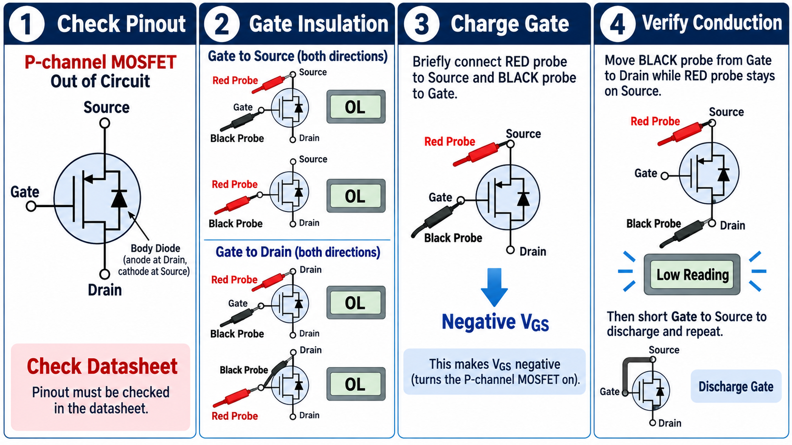
For a conventional P-channel power MOSFET, the intrinsic body diode has its anode at drain and cathode at source. In diode mode, place the red probe on drain and the black probe on source. A healthy silicon device commonly shows a forward drop in roughly the 0.3 to 0.8 V range, depending on device and meter current. Reverse the probes and the reading should normally be open while the gate is discharged.
A near-zero reading in both directions suggests a drain-source short. An open reading in both directions may indicate an open device, an unusual internal structure, wrong pin identification, or insufficient meter test voltage. Body-diode behavior alone does not prove that the controlled channel operates.
If you need a refresher on polarity and channel behavior, see how a MOSFET transistor works.
Step 3: check gate insulation
Measure gate to source with both probe polarities, then gate to drain with both polarities. A healthy discrete MOSFET should normally show open circuit or extremely high resistance on a handheld meter. Some protected MOSFETs include gate-source Zener structures, so consult the datasheet before declaring a finite reading faulty.
A low or stable conductive reading from gate to source or gate to drain usually indicates a punctured gate oxide. Such a device may overload the driver, switch unpredictably, or fail again even if its drain-source path looks normal.
Step 4: turn the P-channel MOSFET on
Begin with gate shorted to source. Put the red probe on source and the black probe briefly on gate. In diode mode the meter applies a polarity that makes the gate lower than the source, creating a negative VGS. The gate capacitance stores this charge.
Keep the red probe on source and move the black probe from gate to drain. A healthy enhancement-mode P-channel MOSFET should now show a much lower reading because the channel is on. Exact displayed voltage depends on the meter, device threshold, and how much gate voltage the meter created. A high-power device may not fully enhance at the meter’s limited voltage, so this is a functional check rather than an RDS(on) measurement.
Short gate to source again. The low drain-source reading should disappear, leaving only the expected body-diode behavior. Repeating the charge and discharge sequence helps distinguish a real gate-controlled channel from a random probe contact.
Why probe polarity is easy to confuse
Many tutorials demonstrate N-channel devices, which turn on with the gate positive relative to source. A P-channel device is the polarity mirror: its source normally sits at the more positive potential, and the gate is pulled lower to turn it on. Do not rely only on red-versus-black memorization, because meters can differ. Reason in terms of VGS and verify the meter’s diode-mode polarity on a known diode.
Testing a P-channel MOSFET in circuit
On a board, first compare resistance from drain to source in both directions with power removed. A short in both directions is suspicious, but a parallel load or another MOSFET can create the same reading. Check gate-to-source voltage while powered only if the equipment can be energized safely and you have the correct reference point.
A high-side P-channel switch normally has its source at the positive supply. It turns off when gate rises close to source and turns on when the driver pulls gate lower. The gate must remain within its absolute maximum VGS rating; a 24 V or automotive system often uses a clamp. For practical switching arrangements, see how to wire a MOSFET.
Common failure patterns
- Drain-source short: near-zero reading both directions after gate discharge.
- Gate short: measurable low resistance from gate to source or drain.
- Channel will not turn on: body diode appears normal, but negative VGS does not reduce drain-source reading.
- Channel will not turn off: drain-source remains low after gate is shorted to source.
- Intermittent hot failure: room-temperature meter test passes, but leakage or RDS(on) becomes excessive under voltage, current, or temperature.
Heating failure analysis is covered in why MOSFETs get hot. A replacement can fail quickly if the original cause was a bad gate driver, inductive overshoot, poor cooling, or a shorted load.
When a multimeter is not enough
Use a curve tracer, source-measure unit, or current-limited test fixture when you need threshold voltage, leakage, transconductance, or on-resistance. RDS(on) must be measured at a specified gate voltage and drain current with a four-wire method or a carefully compensated setup. Datasheet current ratings also depend on case temperature and thermal conditions; they cannot be confirmed by diode mode.
When testing a motherboard or densely parallel circuit, follow the isolation guidance in how to check a MOSFET on a motherboard.
Frequently asked questions
Should source-to-drain read like a diode?
Yes, in one direction the intrinsic body diode usually conducts. For a conventional P-channel MOSFET, the diode conducts from drain to source.
Can I test a P-channel MOSFET without removing it?
You can screen for obvious shorts, but surrounding components may dominate the reading. Isolate the device for a conclusive functional test.
Does a low reading after charging the gate prove full performance?
No. It proves that the channel responds to gate voltage. It does not confirm rated leakage, RDS(on), switching speed, safe operating area, or high-temperature reliability.