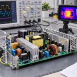
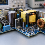
To connect an enclosed switching power supply, first disconnect and verify the absence of mains voltage, confirm the input and output ratings, bond protective earth to the FG terminal and enclosure, connect live and neutral through the required protection, and then connect the DC load between V+ and V-. Test polarity and output voltage before attaching sensitive equipment.
This guide describes the common terminal arrangement used by enclosed single-output AC-DC power supplies. It is not a substitute for the exact manufacturer’s manual, local electrical code, or a qualified electrician. Mains voltage can cause fatal shock, fire, and equipment damage. If the supply has exposed screw terminals or will become part of fixed equipment, the enclosure, disconnect, wire protection, clearances, and earthing must be designed as one system.
Understand the terminals before connecting anything
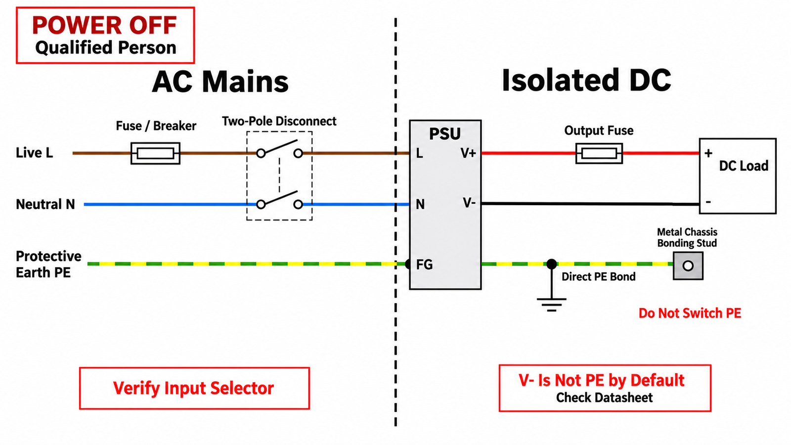
A typical single-phase enclosed supply has input terminals labeled L, N, and FG or with the protective-earth symbol. The output terminals are labeled V+ and V-, sometimes with several parallel terminals for current sharing. Larger supplies may add remote sense, remote on/off, alarm, current-share, or auxiliary terminals. Do not guess their functions from physical position.
- L: the AC live or line conductor.
- N: the AC neutral conductor.
- FG or PE: protective earth or frame ground for a Class I metal-enclosed supply.
- V+: positive DC output.
- V- or COM: negative DC output return.
V- is normally part of the isolated secondary circuit. It is not automatically the same as protective earth. Some systems intentionally bond V- to chassis at one defined point for EMC or safety reasons, while others keep the output floating. Follow the equipment design and datasheet rather than adding an arbitrary link.
Step 1: verify input and output ratings
Read the nameplate and datasheet. Confirm the permitted AC input range, frequency, DC output voltage, continuous current, peak current, operating temperature, and required derating. Some older or low-cost models have a manual 115/230 V selector. Applying 230 V while it is set to 115 V can destroy the supply. Never change a selector while energized.
Check whether the unit is Class I and requires protective earth or is a double-insulated Class II product. A metal enclosed supply with an FG terminal normally requires a permanent PE connection. Also verify whether the model accepts DC input, because L and N labeling alone does not prove DC compatibility.
For the internal conversion stages and why these supplies are efficient, see what a switching power supply is.
Step 2: isolate the circuit and make it safe
- Open the upstream disconnect and apply lockout or another method that prevents accidental reconnection.
- Use an approved meter to verify that the tester works, confirm absence of voltage at the wiring point, then verify the tester again.
- Wait for any specified capacitor discharge time.
- Inspect the supply and enclosure for damage, contamination, loose hardware, or incorrect mounting screws.
- Keep the AC input conductors physically separated from the SELV or other low-voltage output wiring.
A front-panel switch is not always an isolating device. If wiring remains connected to mains upstream of that switch, it can still be hazardous. Provide a suitable branch-circuit breaker, fuse, disconnect, strain relief, and enclosure according to the installation category and local rules.
Step 3: connect protective earth first
For a Class I supply, connect PE directly to the supply FG terminal and the metal enclosure bonding point. Use the specified conductor size, terminal hardware, and torque. Keep this conductor short and mechanically secure. Protective earth must not pass through a fuse, relay, breaker pole, or ordinary power switch.
Remove paint under a bonding stud when the enclosure design requires metal-to-metal contact, and use hardware that resists loosening. The earth path must remain intact even when input power is switched off. After assembly, verify protective-conductor continuity with the appropriate test method for the product standard.
Step 4: wire live and neutral
Route live to L and neutral to N. Live normally passes through the required overcurrent protective device and disconnect. A two-pole disconnect may open both live and neutral where required, but PE remains permanently connected. Wire colors vary by region, so identify conductors by the applicable standard and the actual installation rather than color alone.
Use wire rated for the voltage, temperature, current, enclosure environment, and terminal type. Fit ferrules or listed terminals when required. Keep every strand inside the clamp, avoid tinning stranded wire unless the terminal manufacturer allows it, and tighten to the specified torque. Loose terminals create resistance, heat, arcing, and intermittent resets.
Step 5: connect V+ and V- to the load
Connect supply V+ to load positive and V- to load negative. Check polarity at both ends before applying power. If the supply provides several V+ and V- terminals, they are often internally common and are intended to divide terminal current, but confirm this in the datasheet.
Select the DC conductors from the load current, length, acceptable voltage drop, temperature, bundling, and terminal rating. Place an output fuse or electronic protection near the source when downstream wiring or loads need protection below the supply’s own current limit. The supply’s short-circuit protection may protect the converter without adequately protecting a smaller wire.
Output rectification is one reason polarity matters. The guide to rectifier diodes explains how switched waveforms become DC inside the supply.
Remote sense and control terminals
Remote-sense inputs compensate for voltage drop in the power leads. Connect +S and -S exactly as the manual specifies, normally with a small twisted pair routed to the load. If remote sense is unused, some models require local links from +S to V+ and -S to V-. An open sense lead can cause the output voltage to rise or become unstable.
Remote on/off terminals also vary. Some require a dry contact, some a logic voltage, and some have inverted logic. Never connect them to mains. Current-share and alarm pins are model-specific and should not be tied together without the recommended circuit.
Mounting, cooling, and EMC
Mount the supply in the approved orientation with the specified clearances. Do not block ventilation openings. Supplies with fans need an airflow path and service access. High ambient temperature, altitude, nonstandard orientation, or a sealed enclosure may require output-current derating.
Separate AC input, high-frequency switching nodes, output wiring, and sensitive signal cables. Keep input and output loops compact. Bond shields according to the system EMC design. If a long DC cable feeds a dynamic load, local capacitance at the load may help, but excessive added capacitance can trigger current limiting or stress the supply during startup.
The heat produced inside the converter follows the same loss principles described in why MOSFETs get hot. Adequate airflow and realistic derating protect both the semiconductor switches and electrolytic capacitors.
First power-up procedure
- Inspect the installation with power off. Confirm L, N, FG, V+, and V- against the label.
- Check the input selector and terminal torque.
- Measure resistance between live, neutral, chassis, and output only where the manufacturer’s test procedure permits.
- Disconnect sensitive loads or use a current-limited commissioning setup when appropriate.
- Energize from a protected source and keep clear of exposed mains terminals.
- Measure the unloaded output voltage between V+ and V- with a rated meter.
- Connect the load and verify loaded voltage, current, temperature, fan operation, and abnormal noise.
- Test the upstream disconnect and any system protection.
Do not adjust the output-voltage potentiometer outside its specified range. Raising the voltage may exceed the load rating, output capacitor rating, or overvoltage threshold. The supply should be de-energized before changing wiring.
Common connection mistakes
- Omitting the protective-earth connection on a Class I supply
- Confusing V- with neutral or protective earth
- Using a 115 V selector position on a 230 V supply
- Switching or fusing PE
- Reversing V+ and V- at the load
- Using wire too small for current or voltage drop
- Leaving remote-sense inputs open when local links are required
- Mounting without ventilation or required clearances
- Assuming current limit replaces downstream wire protection
- Working on exposed terminals while energized
When the supply drives MOSFET-controlled loads, verify the load wiring separately. The article on how to wire a MOSFET covers gate, source, drain, and flyback-current paths.
Frequently asked questions
Is V- the same as ground?
V- is the DC return. It may float relative to protective earth. Bond it to chassis only when the system design, EMC plan, or manufacturer’s instructions require that connection.
Can I connect live and neutral either way?
No. Connect live to L and neutral to N as labeled. Protection and filtering may rely on correct polarity even if the converter appears to operate when reversed.
Do I need an output fuse?
Use one when the downstream wire or load needs protection below the supply’s available fault current or current-limit level. Size it from the actual circuit and applicable standard.
Can I install an open-frame or exposed-terminal supply without an enclosure?
Not where users can touch hazardous terminals or where the required fire, mechanical, and insulation protection is absent. Install it inside a suitable end-product enclosure.