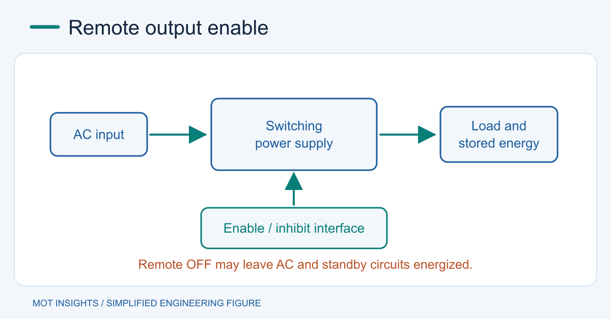
Turn a switching power supply on and off through its documented enable, inhibit or remote ON/OFF input when the model supports it. Check polarity, reference, isolation and what happens if the control wire opens. Remote OFF generally commands output behavior while the AC input can remain energized. Use the equipment’s input isolation procedure before service.
Identify the signal and its reference
Read the exact model’s pinout and truth table. A pin may accept a dry contact, open collector or specified logic levels. Some supplies default to on when a contact is open, and others default to off. For example, MEAN WELL’s RSP-2000 and RSP-750 family documents illustrate opposite remote-contact logic. The matching model manual determines what to connect. Never infer the function from a similar connector or jumper.
Remote sense leads report load voltage, and power-good is usually an output. Keep their wiring separate from enable. If the supply uses a factory jumper for its default configuration, record it and follow the documented replacement wiring. Review the power-supply connection guide for the roles of AC input, DC output and sense terminals.
Design the control interface
Determine the remote pin’s allowable current, voltage and signal reference. An isolated contact or correctly rated isolated interface can be appropriate when controller and supply references differ. Check leakage in the off state and voltage drop in the on state. A relay coil or transistor circuit also needs its own fault and reset behavior.
Design a predictable state when the controller is unpowered, resetting or disconnected. A contact input with default-on behavior may require a different system safety arrangement from a default-off input. In a multi-rail system, use the supply’s timing, status or power-good information and allow the load to reset before its rail falls outside limits.
Decide what off must mean at the load
An output capacitor may hold voltage after disable. A redundant supply or a signal interface can also feed the supposedly disabled rail. Check for auxiliary standby rails and backfeed paths. The Schottky backfeed guide covers one blocking method and its leakage and forward-loss tradeoffs.
For an illustrative isolated discharge path, 470 µF across 1 kΩ has a 0.47 s time constant. An initial 12 V rail would take about 0.84 s to reach 2 V with that resistor alone. The initial resistor power is 0.144 W. Real loads can change the decay curve. Check tolerance, temperature, power and any active discharge circuit. Do not use output decay as evidence that the AC input or primary-side capacitors are safe.
Verify startup, shutdown and abnormal states
Capture enable and output voltage at the supply and load. Record delay, ramp, overshoot, decay, power-good timing and residual voltage. Repeat at minimum and maximum load, with the controller reset and with the enable wire open if the model permits this test. Check a prebiased output and confirm the intended behavior when AC returns after an outage.
For a supply without documented remote control, consider the equipment’s approved input switching method or a suitably rated DC load switch, depending on whether the source or only the load must turn off. The minimum-load guidance helps interpret behavior with the load disconnected. For component selection, share the rail and current requirements with MOT.