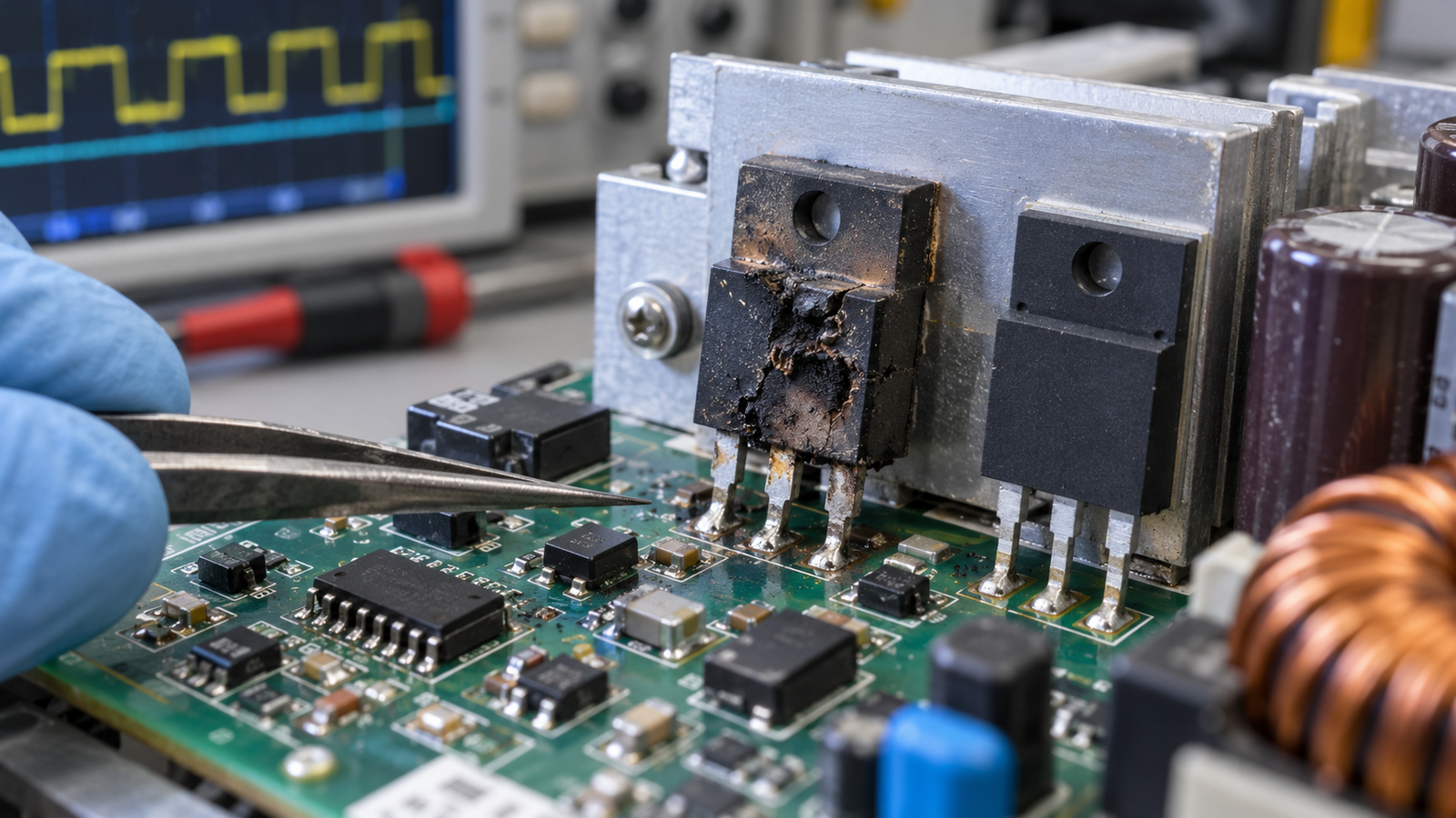
A MOSFET that blows up may fail short, fail open, develop leakage, or damage nearby copper and driver components; the visible damage alone does not identify the root cause.
Power MOSFET failures are energy events. A hard short can vaporize bond wires or silicon, while an open circuit can result from a cracked bond, fuse-like metallization, or a protection path elsewhere opening first.
Start with the exact operating condition
Record whether drain-source is shorted, open, or leaky with all power removed, and inspect the driver, load, clamp, gate network, and source impedance.
Write down the nominal value, its tolerance, the maximum transient, the load waveform, the ambient condition, and what must happen if control power is absent. A familiar part name or a nominal rating does not by itself establish compatibility. The related guide to MOSFET protection provides useful background before hardware is changed.
What the electrical limits mean
Excess VDS, excessive VGS, avalanche energy, overcurrent, linear-mode SOA violation, overheating, shoot-through, and layout-induced ringing can each destroy a MOSFET by different mechanisms.
Compare guaranteed data-sheet limits at the relevant temperature, current, and test configuration. Treat absolute maximum ratings as survival boundaries, not normal operating targets. Include wiring, connector, PCB, and measurement limitations because they can create the same symptom as a component failure.
Design and connection choices
Replace the MOSFET only after correcting the clamp, gate timing, cooling, short-circuit response, or load fault that initiated the stress.
Keep high-current and fast-switching loops compact, provide a defined control reference, and avoid leaving an input floating. If the circuit includes inductance or stored energy, give current a deliberate path during turn-off. safe-operating-area limits covers a closely related implementation decision.
Test before relying on the result
Capture VGS, VDS, current, and temperature during a controlled repeat of the operating condition if safe to do so.
Start at limited available energy where practical. Measure at the device or connector pins rather than only at a remote supply. Test normal load, worst expected load, startup, shutdown, temperature, and one credible fault. A result that works briefly at room temperature is not a complete validation.
Common mistakes to avoid
Do not use a larger current rating as the only fix; it may still have unsuitable gate charge, SOA, avalanche, or package thermal behavior.
When a failure occurs, preserve the failed part and record the waveform, supply condition, load state, and temperature before replacing hardware. Replacing only the visible damaged part can hide an upstream surge, a bad connection, an incorrect drive level, or a load fault.
Build a margin, not a one-condition demonstration
Good engineering decisions separate a component’s stated capability from the capability of the completed assembly. The device data sheet is the starting point, but the circuit also includes leads, connectors, control timing, parasitic inductance, thermal interfaces, enclosure temperature, and the behavior of any upstream source. A design can therefore be electrically plausible on a bench and still have inadequate margin during a cold start, a hot enclosure condition, a wiring disturbance, or a load transient.
Use a small requirement table before selecting parts or changing wiring. Include the normal operating range, worst credible voltage and current, maximum allowable temperature, expected duty cycle, startup and shutdown sequence, fault response, and how each item will be measured. Give every protection part a purpose: a fuse limits available fault energy, a clamp limits voltage, a resistor controls current or edge speed, and a thermal path removes loss. Then verify that each part remains within its own rating while the protection is active.
Measurements deserve the same discipline. A remote meter reading can hide a voltage drop at the device, while a long oscilloscope ground lead can invent ringing that is not actually present. Measure with an appropriate probe, a short reference connection, sufficient bandwidth, and a stated test point. Record the supply setting, load, ambient temperature, configuration, and waveform so that a later result can be compared honestly. When the circuit involves mains or high stored energy, use qualified equipment and procedures rather than experimenting on exposed hardware.
Planning for service is equally useful. Label test points, retain the selected data-sheet revision, and make the intended configuration visible in a schematic, wiring drawing, or build record. A replacement component must reproduce the relevant electrical and thermal characteristics, not merely fit the same package. This simple record shortens fault analysis and prevents a later repair from quietly changing the operating margin.
Finally, decide what a safe failure looks like. If a control signal is absent, a sensor opens, a connector loosens, or a supply brownouts, the circuit should move to a defined state rather than relying on leakage or a floating input. This approach makes the result easier to reproduce, review, service, and scale.
Engineering checklist
For this decision, document the selected part, input range, expected current and voltage, thermal path, protection components, measurement method, and acceptance limits. Confirm that the system remains predictable during reset, brownout, a disconnected signal, and the applicable fault condition. Use avalanche-rating limits as a final cross-check before release.
Frequently asked questions
What is the first check for undefined?
Check whether the device is shorted, open, or leaky before investigating the circuit.
Can a nominal rating prove the design is safe?
No. Use the exact operating waveform, tolerances, temperature, transients, and protection response to establish margin.
Should a failed part simply be replaced?
No. Determine the initiating stress and verify the surrounding circuit before applying full power again.
Why are data-sheet test conditions important?
They define what the quoted number actually means; a different current, temperature, pulse duration, or layout can change the result.
What should be recorded during validation?
Record the exact part number and revision, supply and load conditions, temperature, connection arrangement, instruments, probe points, and observed waveform. This evidence makes a later comparison meaningful and helps distinguish a component limit from a test-setup artifact. Add a short conclusion stating whether the result met the original requirement, what margin remained, and which limit should be checked again if the operating condition changes.