The 10V-driven SiC MOSFET is reshaping its power semiconductor application pattern, and on-site application engineers are well aware of the challenges that clients face in adopting SiC technology. Traditional 650V SiC MOSFET usually requires 15V-20V drive voltage, which is incompatible with the widely used 10V-driven silicon superstitions of MOSFET (CoolMOS), which directly increases system replacement costs and design complexity.
Now, the emergence of the 10V drive 650-800V SiC MOSFET technology is changing the situation. This innovation, through 27nm hyperbunker oxygen design and gutter optimization, achieves perfect compatibility with conventional silicon-driven circuits while maintaining the excellence of the SiC device.
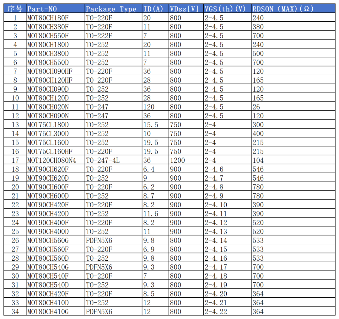
01 Technical background and market demand
Why do 10V drive SiC MOSFET?
In the power semiconductor area, compatibility is often a key factor in the speed of technology diffusion. Most commercial power systems are currently designed for a 10V-driven silicon superstition MOSFET, including photovoltaic voltage converters, modular multilevel converters and power factor correction pressure converters.
When the client wishes to upgrade the Siliconware in the system to SiC MOSFET, it faces a difficult problem: the drive is incompatible. The traditional SiC MOSFET requires a higher drive voltage (15V flat, 18V groove) and direct replacement leads to performance failure, while redesigning the drive circuit increases costs and development cycles.
Technology Breakpoint
The new 10V drive 650-800 V SiC MOSFET solves this problem through an innovation device structure. The MOT's Taiwan and Nanjing research teams have designed three different components: ASPM-1 (0. 5 μm ditch), ASPM-2 (0. 3 μm ditch) and ASPM-3 (0. 5 μm ditch + partition) using 27 nm fence thickness.
Studies have shown that excellent conductivity and switch properties can be achieved with a 10V drive by optimizing the length of the ditch and the oxygen thickness of the fence. Specifically, the SiC MOSFET (ASPM-2), which is designed with 0. 3 μm troughs, can be reduced to 115 m, or 1. 39 times lower than the traditional SiC MOSFET, or even better than 180 m of CoolMOS products, at 10V power.
02 Technical challenges and solutions
Steering resistance challenge at low-driving voltage
In the traditional SiC MOSFET, over-drive voltage (Vgs-Vth) is reduced as the drive voltage is reduced, leading to a significant increase in groove resistance. This is the main technical obstacle to achieving the 10V drive.
The calculation formula for electrical resistance in the ditch clearly explains the phenomenon:
Lch Wcell Rch, SP = 2 mmni Cox (Vgs-Vth)
Of these, the decrease in Vgs-driven voltage directly leads to an increase in electrical resistance over the ditch.
Innovative device structure optimization
To address this problem, researchers have developed three different 10V drives of 650V SiC MOSFET device structures:
1. ASPM-1: 0. 5 μm length of ditch, standard fence structure
2. ASPM-2: 0. 3 μm Tunnel length, standard fence polar structure
3. ASPM-3: 0. 5 μm length of ditch, partition structure
All three components are manufactured using 27nm fence oxygen thickness on the 6-inch Silicon carbide production line in X-Fab. Of these, ASPM-2 has designed the short ditch path to cross the traditional design 1. 8 times, and the fencing capacity has increased significantly, achieving faster switch speeds and lower switch losses.
Reliability safeguards
The thin-stretch oxygen and short ditch designs, while improving performance, also pose reliability risks. To this end, researchers have adopted the following key technical safeguards:
· Accurate mixing control: P-base concentration 3e16cm3, JFET concentration 5. 4e16cm3
P-shield structure: concentration 1e18cm-3 effective suppression of penetration risk
Rigorous process monitoring: ensure long-term reliability of 27 nm flaring oxygen
The measured data show that the leaks of these devices under the 650V rated shut-down voltage were below 0. 1 μA, and the penetration of the voltage reached 850 V proved their reliability.
03 Performance comparison and advantage analysis
Static Parameter Comparison
Below is the performance comparison of the 10V drive 650V SiC MOSFET with the traditional CoolMOS:
| Parameters | ASPM-2 (SiC) | CoolMOS (Si) | Advantages |
| Breaking voltage (BV) | 850 V | 710 V | +19. 7% |
| Convey electrical resistance (Ron) | 115 times. | 180 times. | -36. 1%. |
| Threshold voltage (Vth) | 1. 8V | 3. 5 V | Lower fence demand. |
| Cross-guide (Gm) | 13S | 7S | +85. 7% |
As can be seen from the comparison data, the 10V driven SiC MOSFET completely transcends the traditional Silicon Hypothesis MOSFET in key static parameters.
Dynamic performance advantage
With regard to switch properties, the 10V driver SiC MOSFET also performed excellently:
• Significant reduction in switch losses: ASPM-2 total switch losses were 148 mJ, while CoolMOS was as high as 2705 mJ, more than ten times different
• Reverse restoration feature improvement: The reverse recovery charge for SiC MOSFET is only about 1/5 of a silicon device, significantly reducing switch noise and EMI
• Frequency feature enhancement: at all frequencies, SiC MOSFET lost less power than CoolMOS
Comparative Capacitive Characteristics
Capacitive properties are key factors influencing switch performance. The 10V drive, SiC MOSFET, shows a unique advantage with regard to the electricity:
Under high pressure conditions (Vds = 400V), Sic MOSFET has a Coss value of 95-97 pF, while CoolMOS is 17pF; however, under low pressure conditions (Vds = 1V), Sic MOSFET Coss is 600-620 pF and CoolMOS has up to 13, 000 pF.
This feature requires CoolMOS to charge its large low-pressure output capacitor during the switch, significantly slowing switch speed and increasing switch loss, while SiC MOSFET avoids the problem.
04 Keys for driving circuit design
Fence-driven voltage optimization
While the device itself has been optimized for the 10V drive, the design details of the motor circuit need to be taken into account in its application:
Optimizing pressurization: It is recommended to use a 10V ± 5% drive voltage to ensure that the device is fully connected while avoiding overdrive.
Negative pressure break consideration: For high-speed switch applications -3V to -5V can be considered for a closed negative pressure to prevent error triggered by a string disturbance.
Fence barrier choice.
The right grid is critical to balancing switch speed with EMI:
• Optimization of electrical resistance: based on the actual application scene, the barrier is usually selected between 2. 2 and 10 times
• Power capacity: select high switch frequency, high power grid extreme resistance, preventing temperature escalation High
Protection of circuit design
The short circuit duration of SiC MOSFET is usually shorter than the IGBT (2-4 ms vs 10 ms) and requires faster protection mechanisms:
Two-altitude break-up protection: When short circuits are detected, the grid is reduced to an intermediate level (e. g. 5V) and then completely disabled, reducing the short circuit current stress.
Source Miller Clip: Integrated Miller Clip function to prevent high dv/dt-induced parasitic guidance and enhance system reliability.
05 Practical application scene and performance validation
AI Server Power In the AI server power source, the 10V drive 650 – 800 V Si C MOSFET can have significant advantages: efficiency gains: 98. 2 per cent efficiency of the SiC programme under 1kW output conditions, 96. 5 per cent for the excess MOSFET, and significant improvements.
Electrical vehicle chargers: In XEV vehicle chargers, 10V driver SiC MOSFET can simplify driver designs and improve system efficiency.
Solar Photovoltaic Reverser: In photovoltaic applications, the direct replacement feature of the 10V drive SiC MOSFET significantly reduces the cost of upgrading: compatibility advantage: it can directly replace the original silicon MOSFET without the need to modify the driving circuit and significantly reduce the cost of adaptation.
06 FAE Perspective Design proposal
Selection Guide
Based on the different applications, I propose the following alternative strategy:
High-efficiency high-frequency applications: Prioritize short-course designs (e. g. ASPM-2) to achieve optimal switch performance using their high cross-conductor properties.
High Reliability Application: Select a device (e. g. ASPM-3) for the partition structure to enhance reliability while ensuring performance.
PCB Layout Optimization: In order to optimize the performance of the 10V drive SiC MOSFET, PCB Layout requires special attention:
Low parasitic sense: optimized layout, reduced parasitic sense driving circuits and power circuits, inhibited voltage peaks and ringing bells.
Thermal design enhancements: use large areas of copper beams and heat vents to ensure that the temperature of the device is within safe limits.
The 10-V drive 650-800 V SEC MOSFET will be the ideal alternative to the Silicon Hypothesis MOSFET as the technology matures. This innovative technology not only preserves the high-frequency efficiency advantage of the SiC material, but also addresses the compatibility with conventionally driven circuits.
For power designers, this means that efficiency gains and volume reductions associated with SiC technology can be enjoyed without changing the current driver structure. As more manufacturers join this technology route, the 10V drive SiC MOSFET is expected to spread rapidly in the areas of server power, electric car chargers and photovoltaic retroverts.