You can change a MOSFET’s effective threshold with body bias when the body terminal is independently accessible and the technology supports that bias. A typical three-terminal discrete power MOSFET has its body tied to its source. In that case choose a different device or change the gate drive to meet the switching requirement. Temperature also shifts the observed threshold.
Establish which threshold you are comparing
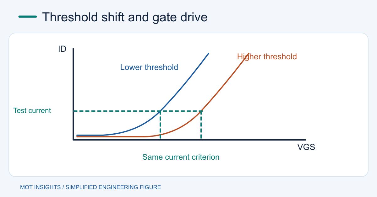
A datasheet specifies VGS(th) at a stated drain current, drain bias and temperature. An extracted value from a transfer curve can differ if the method or conditions change. Use a consistent criterion before deciding a part has drifted. The threshold-voltage extraction guide describes why two legitimate methods can report different values.
For power switching, a threshold test at a small current only establishes a reference for the onset of conduction. Use maximum RDS(on) at the gate voltage the circuit can actually deliver to estimate full-load loss. If the datasheet guarantees resistance at 4.5 V and the controller only guarantees 3.0 V at its output, the resistance specification does not establish performance in that circuit. Check the minimum drive after driver drop and source bounce.
How body bias changes an integrated NMOS
For the classical long-channel NMOS body-effect model, VTH = VTH0 + γ[√(2φF + VSB) − √(2φF)]. VSB is source voltage relative to the body, 2φF is the positive surface-potential term in volts, and γ is a process parameter in √V. Increasing reverse source-to-body bias raises the threshold in this model. For PMOS use its process model and sign convention.
In integrated designs, a supported forward body bias can reduce threshold magnitude within the foundry limits. Excess forward bias can inject junction current and create reliability or latch-up problems. Modern processes may behave differently from the simple square-root model. Read the process design kit for allowed voltage range, leakage and device models. Circuit designers can also choose a low- or high-threshold transistor variant if the process offers one.
What changes on a discrete power board
Moving a three-terminal device’s source shifts its gate-to-source voltage if the gate stays fixed. The internal body-to-source connection remains. For example, a gate at 5 V relative to board ground produces only 3 V of VGS when the source is at 2 V. Use source-referenced VGS calculations for high-side or source-degenerated stages.
To turn on harder, select a driver and device whose guaranteed conditions overlap. To keep a device off under fast switching, use a firm source-referenced pull-down, good return layout, and a Miller clamp or negative off bias only when the driver and device allow it. Negative off bias changes the gate operating point. The maximum positive and negative VGS ratings still apply during overshoot and ringing.
Separate temperature and aging from bias
Many silicon MOSFETs exhibit lower threshold at higher junction temperature in the low-current threshold test. Meanwhile, fully enhanced RDS(on) generally rises. A device can therefore start to conduct at a lower gate voltage when hot and still dissipate more power at its normal load current. Use the curves and the NMOS threshold temperature discussion to interpret the measurement.
Compare suspect parts using a current-limited fixture and repeatable pulse conditions. Record VDS, drain-current criterion and temperature. Unexpected shifts after stress warrant checking gate leakage and comparing against an unstressed sample. Changing the circuit bias can compensate for a designed operating variation, while device damage calls for fault diagnosis and replacement.
Choose the practical change
For a 3.3 V GPIO driving a slow low-side switch, compare the guaranteed output level against guaranteed on-resistance, then verify startup and temperature. For an analog stage, set a bias current and evaluate its spread with corner models. For a high-dV/dt half-bridge, prioritize off-state immunity as well as on-loss. Compare candidate power MOSFETs using the voltage and temperature conditions your circuit can maintain.