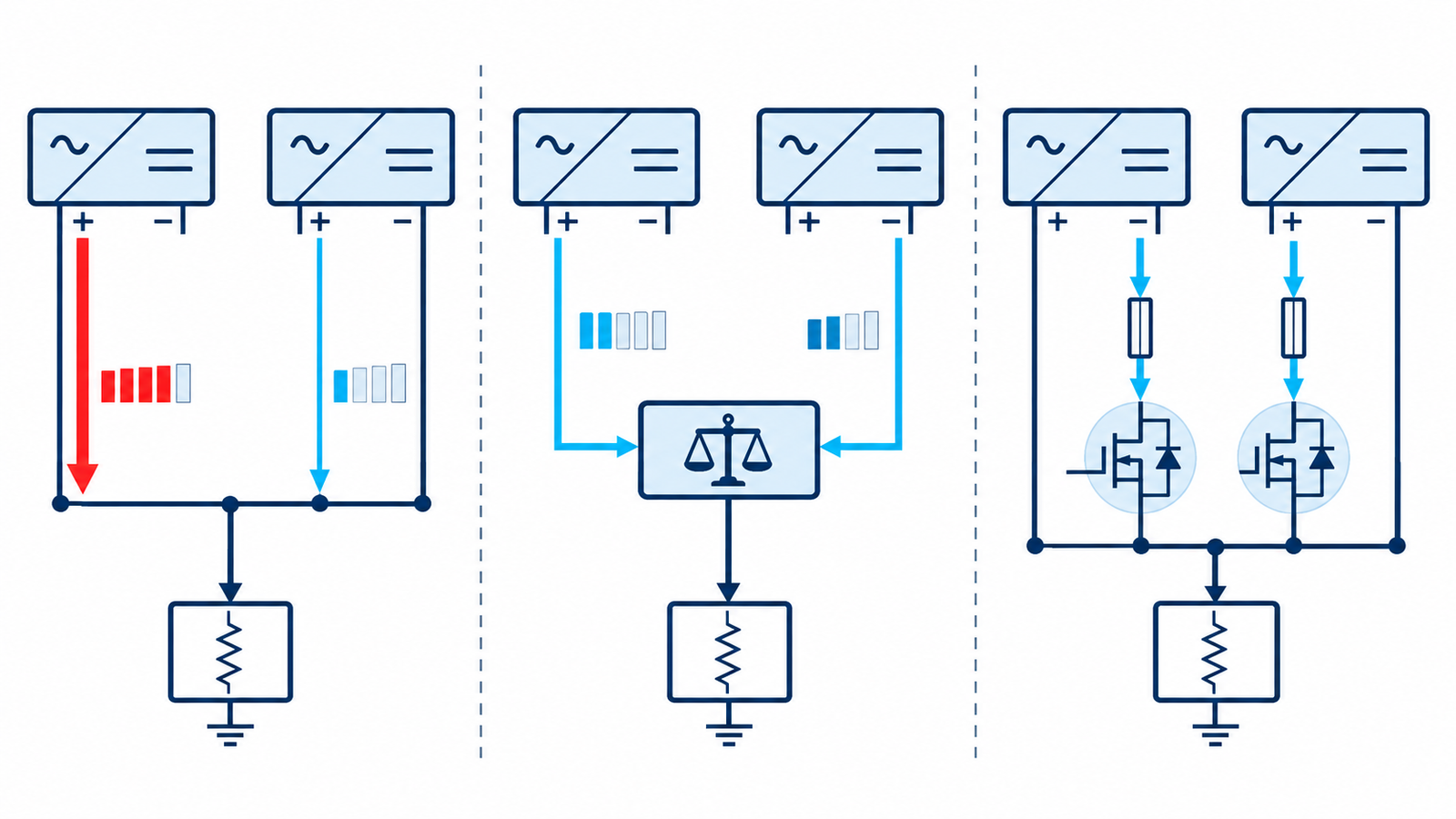
Connect two switching power supplies in parallel only if the manufacturer explicitly supports the configuration and you use its prescribed sharing or redundancy method. Two independent regulated outputs are never exactly equal. Without coordination, the slightly higher-voltage unit can supply nearly all the load until it current-limits, while the other contributes little. Some outputs can also be damaged by reverse current.
First decide whether the goal is more current, N+1 redundancy, or both. Current sharing tries to divide load. Redundancy tries to keep the bus alive after one input or supply fails. These goals use related but not identical circuits.
Why direct output connection is risky
Each supply has a voltage tolerance and feedback loop. If supply A regulates only tens of millivolts above supply B, A initially carries the load. As its droop or current limit begins, B may join abruptly. The loops can interact, oscillate, or cycle through hiccup protection. An unpowered unit may sink current through its output stage.
The foundation in how switching power supplies regulate explains why two closed loops do not automatically share.
Use an active current-share bus when available
Many modular and telecom supplies provide SHARE, I-share, or parallel pins. These coordinate current commands so modules carry similar fractions of the load. Follow the manual for the number of units, wire length, grounding, startup sequence, minimum load, remote sense, and required trim settings. Do not connect unrelated share pins merely because labels look similar.
Some architectures appoint a master; others average module currents. A failure in the share connection must not command damaging output voltage. Validate open, shorted, and miswired share-bus faults where the application requires high availability.
Understand droop sharing
Droop sharing intentionally reduces output voltage as current increases. Supplies with matched droop curves settle at a shared operating point without a communication wire. Distribution resistance can also create accidental droop, but relying on uncontrolled cable loss gives poor regulation and unpredictable sharing.
Set both units according to the approved procedure and use equal-length, equal-gauge output conductors or a symmetric busbar. Measure current in each branch at several total loads and temperatures. Small no-load voltage differences can become large current imbalances when output impedance is low.
Add OR-ing for redundancy
Diode OR-ing prevents one output from backfeeding another and lets the healthy source maintain the bus. Schottky diodes are simple at low voltage but dissipate I×VF. Ideal-diode controllers and MOSFETs reduce drop while requiring careful transient, reverse-current, and failure analysis. Provide a separate fuse or breaker for each branch.
Redundancy also requires independent upstream energy. Two supplies on the same fuse, connector, AC feed, cooling fan, or control signal may share a single point of failure. See when Schottky OR-ing is appropriate for diode tradeoffs.
Wire remote sense and grounding correctly
Remote-sense leads should observe the intended common load point and must follow the manufacturer’s parallel instructions. Independent sense loops connected incorrectly can fight through the power wiring. Protect sense leads against open circuits and observe maximum compensation limits.
Decide whether negative outputs are isolated, bonded, or tied to protective earth. Do not parallel outputs if their allowed common-mode voltages or isolation classes conflict. Keep high-current paths short, symmetrical, and rated for the combined fault current.
Commission the system methodically
Confirm each supply alone, then connect sharing and OR-ing components with current-limited sources where possible. Compare no-load voltages, start and stop timing, current split, ripple, transient response, and temperature from light load through maximum continuous load. Test minimum and maximum input conditions.
Disconnect one input, short or current-limit one output under an approved test plan, and confirm the healthy unit does not exceed its rating. Check recovery from overload and hiccup. The design workflow in switch-mode power-supply design helps frame loop, layout, protection, and thermal review.
Engineering checklist
Obtain written approval in the product manual for the exact supply model and revision. Record maximum combined current, required derating, share accuracy, output-capacitor limits, OR-ing loss, connector temperature, cable drop, and response after module removal. Remember that two 10 A supplies may not create a guaranteed 20 A system once sharing tolerance and redundancy reserve are included.
Log branch current as well as total current during commissioning. A correct bus voltage can hide a badly overloaded module. Set an alarm threshold for persistent imbalance, and ensure monitoring circuits do not create a new backfeed path between otherwise isolated sources.
For N+1 service, keep the remaining units below their continuous ratings after any one unit is lost. Add monitoring that distinguishes input failure, output failure, fan failure, overtemperature, and share imbalance. Test faults at hot ambient and maximum load. Never hot-plug a module unless its connectors, inrush control, grounding sequence, and manufacturer instructions support it. Mains-side work must be performed by qualified personnel in a compliant enclosure.
Frequently asked questions
Can I parallel two 12 V adapters to get more current?
Not unless both adapters are explicitly designed and documented for parallel operation. Small voltage differences can prevent sharing or cause reverse current.
Do OR-ing diodes make supplies share current equally?
No. They isolate outputs for redundancy, but current sharing still depends on voltage, droop, resistance, or an active share controller.
Should both supplies be adjusted to exactly the same voltage?
Follow the specified procedure. Matching helps but does not replace an approved sharing method, and meters cannot eliminate dynamic tolerance.
Can supplies with different current ratings be paralleled?
Only if the manufacturers and sharing architecture support proportional sharing between those exact models.