CCM in a switch-mode power supply means continuous conduction mode. The current in the energy-transfer inductor does not fall to zero during any switching cycle at the stated operating point. It rises during one interval and falls during another, but a positive current remains when the next cycle begins.
CCM is not a permanent label for every converter. A design can operate in CCM at full load, boundary conduction near a transition point, and discontinuous conduction mode (DCM) at light load. The mode affects equations, waveforms, losses, magnetics, control, and component stress.
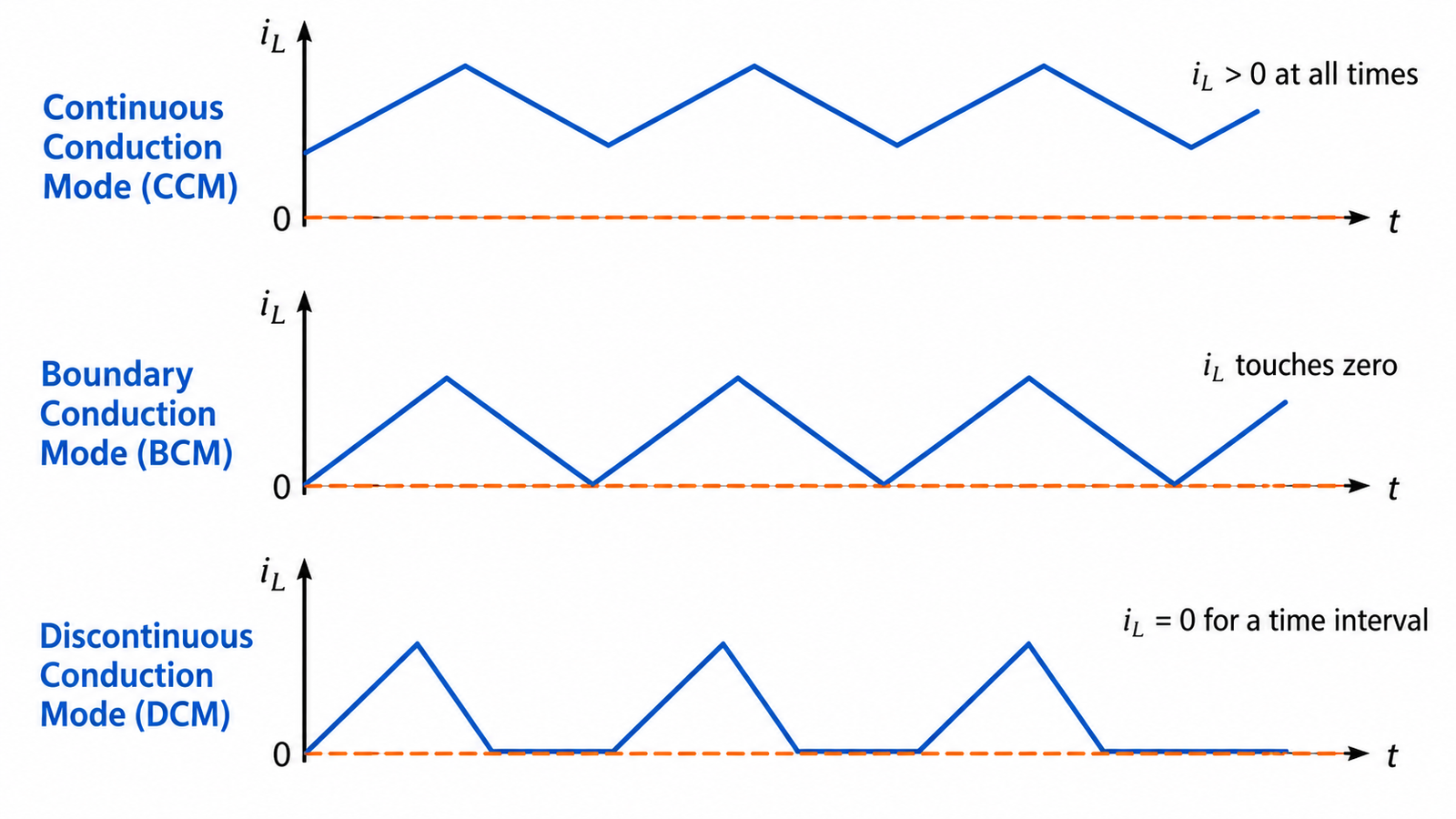
Recognize CCM on the current waveform
Observe the inductor current over multiple steady-state cycles. In CCM, the triangular ripple rides on a DC level and its valley remains above zero. At the boundary, the valley just touches zero. In DCM, a third interval appears in which inductor current is zero before the next cycle.
Do not infer the mode only from output current. Turns ratio, topology, ripple current, and where the current is measured matter. Current-probe bandwidth and offset can also hide a small zero-current interval.
What sets the conduction mode
Load current, inductance, switching frequency, input voltage, output voltage, and topology determine the ripple and average current. Increasing inductance or frequency usually reduces ripple and can extend CCM toward lighter load. Lower load tends to move a converter toward boundary mode and DCM. Controllers may deliberately enter pulse skipping or burst mode, creating behavior outside the textbook fixed-frequency cases.
The overview of SMPS design explains why mode selection must follow the complete input and load range.
CCM in a buck converter
For an ideal buck converter in steady CCM, the familiar duty-cycle relationship is approximately VOUT/VIN. Inductor ripple is set by the voltage across the inductor, on and off times, inductance, and frequency. Real switch drops, diode or synchronous-FET drops, dead time, winding resistance, and control delays modify the result.
The switch carries the inductor current during its on interval; the diode or low-side MOSFET carries it during the off interval. RMS current, not only average output current, sets conduction loss.
Benefits and tradeoffs
Compared with DCM at the same power, CCM often has lower peak current and lower RMS stress, which can reduce conduction loss and filtering burden. The inductor may need more energy storage and must avoid saturation at peak current. In a diode converter, continuous current can make reverse recovery more important when the switch turns on.
CCM also changes the control plant. Some topologies introduce a right-half-plane zero or require slope compensation in peak-current-mode control above certain duty cycles. Compensation must match the actual mode and operating point.
CCM during startup and faults
At startup, the output capacitor can demand high current before normal regulation is established. Current limit, soft start, transformer flux balance, and inductor saturation need explicit review. During a short circuit, the controller may enter hiccup, foldback, pulse skipping, or a fixed current limit, so steady-state CCM equations no longer describe the converter.
Understanding the complete switching power-supply architecture helps place the CCM waveform within sensing and protection loops.
Verify mode across the operating map
Calculate and simulate minimum and maximum input, load, frequency, inductance tolerance, and temperature. Then measure inductor or switch current with a safe, properly degaussed probe. Check the valley against zero, peak against saturation and current-limit thresholds, and RMS values against thermal ratings.
Repeat during load steps and light-load mode transitions. Confirm the compensation, ripple, audible behavior, and efficiency in every intended operating mode rather than optimizing one nominal CCM point.
Turn the answer into a design decision
For What Does CCM Mean in a Switch-Mode Power Supply?, write a one-page operating specification before selecting hardware or changing a circuit. Include input range, output range, continuous and transient load, allowed ripple, startup time, hold-up requirement, ambient range, airflow, enclosure, isolation, grounding, and abnormal conditions. Separate facts taken from official documentation from assumptions that still need measurement. This prevents a familiar topology name from being mistaken for a complete specification.
Create an operating-corner matrix covering low and high input, light and heavy load, hot and cold conditions, startup into a discharged output, load removal, brownout, and restart after protection. For each corner, identify the most stressed switch, diode or synchronous device, magnetic component, capacitor, connector, and control signal. Then define pass limits before testing. A converter that regulates at room-temperature nominal load may still have inadequate voltage margin, unstable light-load behavior, excessive hot capacitor ripple, or a protection mode that repeatedly overstresses the same component.
Document the instruments, probe points, bandwidth limits, and safety method used for every result. Save waveforms rather than only writing down meter readings. When the unit is part of a certified or industrial system, preserve approved part numbers, wiring rules, and enclosure requirements; do not convert a descriptive article into authorization for an undocumented substitution. Sign off the design only when normal performance, worst-case stress, recovery after faults, thermal equilibrium, and production tolerances have all been addressed.
Practical validation checklist
Verify the exact product or converter at minimum and maximum input, no load, normal load, and rated load. Record output voltage, ripple, startup, shutdown, load-step response, component temperature, audible noise, and protection recovery. A stable average reading does not prove that switch-node ringing, control-loop oscillation, or peak device stress is acceptable. Use probes and instruments rated for the circuit, keep measurement loops short, and never defeat protective earth or enclosure interlocks.
For a new design, review magnetics, semiconductor voltage and current margins, capacitor ripple current, loop compensation, creepage, clearance, thermal derating, and abnormal-fault behavior together. The broader switch-mode power-supply design workflow helps turn a topology choice into a verifiable product.
Frequently asked questions
Does CCM mean constant current?
No. Inductor current contains ripple and changes with load; continuous means it does not reach zero within the switching cycle.
Is CCM always more efficient than DCM?
No. Efficiency depends on topology, load, switching loss, conduction loss, magnetics, and control strategy.
Can a flyback converter operate in CCM?
Yes, although current is stored in the coupled inductor and transferred during different intervals; CCM changes stress and control behavior.
How do I know the CCM boundary?
Calculate where the inductor-current valley reaches zero, then verify with tolerances and measured waveforms.