A kilowatt-class switch-mode regulated high-voltage power supply converts an input source into a controlled high-voltage output by switching energy at high frequency, stepping it through isolated magnetics, rectifying it, and closing feedback around voltage or current. Typical applications include industrial electrostatics, test equipment, scientific instruments, plasma, charging, imaging, and beam systems.
This article explains architecture and design review, not construction instructions. Kilowatt power combined with high voltage can cause fatal shock, arc flash, fire, X-ray generation in some loads, and dangerous stored energy after shutdown. Development belongs in properly equipped laboratories with trained personnel, interlocks, barriers, certified components, and documented safety procedures.
Input stage and intermediate bus
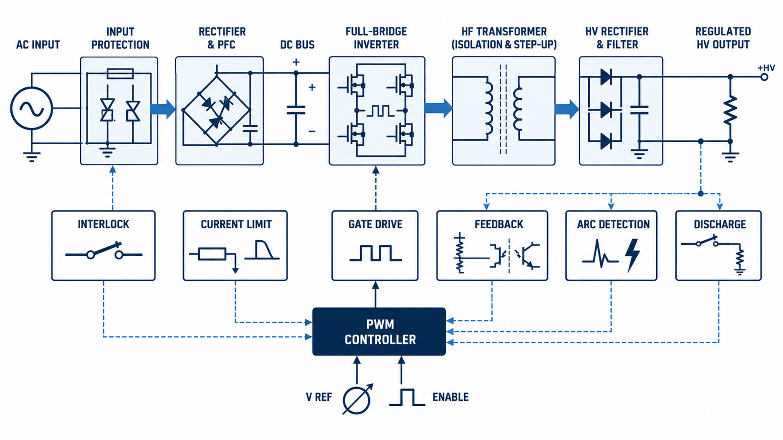
The front end may include fusing, contactors, surge protection, EMI filtering, inrush limiting, rectification, and active power-factor correction. It creates a controlled DC link for the high-frequency inverter. At kilowatt power, capacitor ripple current, line harmonics, brownout behavior, precharge, and fault clearing are system-level concerns.
The bus stores substantial energy. A discharge network, monitored contactor state, and safe-access delay are required. Protective earth and chassis bonding must be designed independently of signal ground. The overview of switching-power-supply architecture provides the lower-power foundation.
High-frequency inverter and control
A half bridge, full bridge, phase-shifted bridge, resonant converter, or other isolated topology drives the primary. MOSFETs, IGBTs, SiC MOSFETs, or other switches are selected by bus voltage, frequency, current, switching loss, fault robustness, and available drivers. Resonant operation can reduce switching stress but makes tank tolerance and load range important.
Gate drivers need isolation, undervoltage lockout, controlled dead time, low-inductance loops, and immunity to high dV/dt. The guidance on protecting MOSFETs from dV/dt is especially relevant to fast high-voltage bridges.
Step-up transformer and insulation system
The transformer provides voltage conversion and safety isolation. Winding geometry must balance leakage inductance, interwinding capacitance, copper loss, core loss, partial discharge, creepage, clearance, and thermal rise. High-frequency voltage distribution within a winding can be nonuniform, so insulation design is more complex than choosing turns ratio.
Potting or oil can improve dielectric performance but introduces void, contamination, service, and thermal-expansion risks. Insulation materials, bobbins, margins, shielding, and production tests must conform to the relevant working voltage, pollution degree, altitude, overvoltage category, and standards.
High-voltage rectification and filtering
The secondary may use diode stacks, multipliers, center-tapped arrangements, or bridge structures. Each device must share static and dynamic reverse voltage. Recovery, capacitance, leakage, temperature coefficient, physical spacing, and equalization networks affect sharing. Parasitic capacitance can return high-frequency common-mode current through the chassis and control system.
Output capacitors and cables store energy proportional to capacitance and voltage squared. Limit available arc energy, provide a bleeder and verified discharge path, and consider series resistance or active current limiting. An unloaded terminal can remain hazardous long after switching stops.
Feedback, regulation, and arc response
High-value dividers or isolated sensing scale output voltage into the controller. Divider voltage coefficient, leakage, layout, contamination, corona, and bandwidth affect accuracy. Current sensing may be primary referred or directly isolated. The loop must remain stable from open circuit to full load and during transitions between voltage regulation and current limiting.
An arc can collapse output voltage while releasing stored energy and provoking maximum controller demand. Fast detection, pulse-by-pulse limiting, inverter shutdown, controlled restart, and event counting may be required. Recovery logic should avoid repeated destructive arcing.
Thermal, EMC, and validation
Loss is distributed among switches, magnetics, rectifiers, bus capacitors, snubbers, bleeders, and filters. Airflow near high electric fields can move dust and alter corona behavior. Thermal monitoring should cover the parts whose time constants and failure modes matter, not just the easiest heatsink.
Validate regulation, ripple, efficiency, temperature, conducted and radiated emissions, dielectric strength, partial discharge where applicable, abnormal load, open circuit, short circuit, arc, fan failure, sensor failure, and interlock operation. The structured approach in designing an SMPS remains useful, but high voltage adds specialized insulation and stored-energy analysis.
Engineering checklist
Begin with a requirements and hazard specification: input range, output voltage and polarity, power, current limit, ripple, stored-energy ceiling, load capacitance, arc rate, isolation class, altitude, environment, duty cycle, communication, and applicable standards. Partition the system so hazardous nodes are inaccessible and diagnostics do not compromise isolation. Favor certified high-voltage modules when a custom power stage is not a core competency.
Design independent protection layers for overvoltage, overcurrent, overtemperature, loss of feedback, transformer saturation, fan failure, open enclosure, stuck control, and failure to discharge. Use interlocked enclosures, remote enable, emergency off, grounding sticks where procedures require them, and measurement equipment rated for the voltage and energy. Formal design review, hipot and partial-discharge expertise, production traceability, and service documentation are essential.
Frequently asked questions
What topology is used for a kilowatt high-voltage SMPS?
Half-bridge, full-bridge, phase-shifted, and resonant topologies are common; the correct choice depends on input, voltage ratio, load range, switching frequency, and fault requirements.
Why use high frequency instead of a line-frequency transformer?
Higher frequency can reduce magnetic size and improve control bandwidth, but increases switching, insulation, parasitic, and EMI challenges.
Can a voltage multiplier deliver kilowatt power?
Multipliers can deliver substantial power in specialized designs, but diode, capacitor, ripple, impedance, cooling, and stored-energy stresses grow quickly.
Is the output safe after shutdown?
Not automatically. Capacitors and cables can retain lethal energy, so a designed, monitored discharge path and safe-access procedure are mandatory.