A MOSFET in a switching power supply can warm up at no load because the converter still switches, powers its own circuits or circulates current. A device that keeps getting hotter, a rail that oscillates, or standby input power above the supply’s specification warrants investigation. Compare the operating mode, real input watts and temperature before deciding whether the MOSFET or its surroundings are responsible.
Define what idle means on this supply
Separate three states before taking a reading. A supply can be enabled with all external loads disconnected, enabled with a system in standby, or disabled through its remote input. Those states can keep different rails active. An output capacitor being charged by periodic bursts, a preload resistor and a housekeeping converter can all draw power with zero external load. A USB interface or second supply can feed the board through an alternate path. If the product specifies a minimum load, compare it only under the conditions in that specification. Minimum-load behavior
Identify which transistor gets warm. An AC/DC unit can have a PFC switch, a main converter switch and separate output rectifiers. Temperature at a switch next to a hot transformer or heatsink reflects thermal coupling as well as the switch’s own dissipation. Compare temperatures at repeatable points and with the enclosure and airflow specified for the unit. Give temperatures time to settle. A brief rise after the load is removed can reflect heat already stored in the assembly.
Find out whether the switch is still working
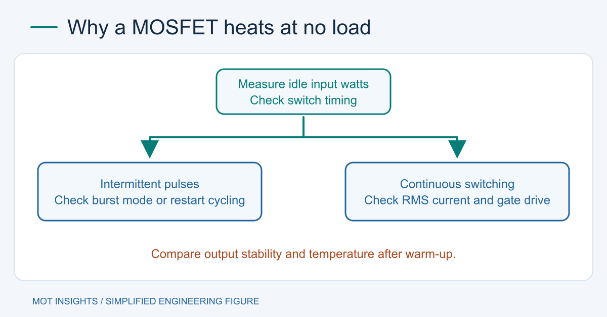
An enabled converter may keep switching at nearly fixed frequency, skip individual pulses, or send short groups of pulses separated by idle intervals. These are valid control behaviors when documented for the device. Check switch-node timing and output ripple over several burst periods. A short scope capture can show continuous pulses inside a burst while missing the long quiet interval that determines average loss.
A hard-switched stage can expend energy charging and discharging device capacitances even when useful load current is small. Driver power for complete on-off cycles is approximately Qg × Vdrive × f, with Qg in coulombs, drive swing in volts and completed cycles per second. At 30 nC, 10 V and 250 kHz, this is 75 mW delivered to the gate-drive network. The driver and gate resistances share that energy. Other losses include drain-capacitance energy, switching overlap and bias power. Estimate the actual time spent switching or use a window that captures the complete burst pattern.
In a synchronous buck that allows negative inductor current, current can flow in both directions at light load. A slow meter at the output can read nearly zero average current even though the switches carry RMS current and dissipate I²R loss. A diode-emulation mode can stop the low-side device near the current zero crossing if the controller supports it. Verify the configured mode and current waveform. The high-side and low-side heating guide explains how switching transitions, dead time and cooling distribute the heat.
Use input watts and temperature together
Disconnect the external DC load where the equipment permits it and verify the output remains within range. Record input voltage, outlet state, converter enable, output voltage and the surface temperature after stabilization. On AC input, use a suitably rated meter that reads real watts and can resolve low standby power. Average for long enough to include skip or burst activity. Repeat under a small, documented load and compare both points with the manufacturer’s limits. Power supply efficiency measurement
| What you observe | What to verify |
|---|---|
| Low steady input power and a warm switch beside another hot part | Compare temperatures across the board and verify thermal coupling. |
| Repetitive short pulse groups with a stable rail | Check the controller’s burst mode description and average input power. |
| High input power and continuous switching near zero external load | Check mode settings, preload, auxiliary loads and bidirectional inductor current. |
| Repeated startup with a collapsing rail | Check bias voltage, feedback and protection timing for retry cycles. |
| Heating while disabled | Check which rails stay live and whether another cable energizes the output. |
An idle power reading is a system total. To locate the loss in a low-voltage prototype, check VGS at the MOSFET terminals, drain transitions and inductor current. Gate bumps when the opposite device turns on can reveal false turn-on. A falling driver rail can leave a MOSFET weakly enhanced. Confirm that changes to dead time or gate drive improve losses without increasing overshoot or switching stress.
Know when to stop the test
Stop if temperature keeps climbing, the output drifts, or there is odor, discoloration or cycling protection. Internal measurements on mains-powered units belong to qualified personnel using rated equipment. Bulk capacitors may remain charged after disconnection. Never attach an earth-referenced oscilloscope ground clip to a floating primary node.
Before changing devices, record idle watts, operating mode, gate voltage and maximum switch voltage. If the data point to the switch itself, compare candidates at the measured drive and drain conditions, or share the measurements with MOT technical support.