A regulated power supply holds a specified output within stated limits as conditions such as input voltage and load vary. A switching power supply uses a switched power stage to convert energy. A supply can be both regulated and switching, and a linear supply can also be regulated. Use the output specifications to judge regulation and the topology to understand efficiency, ripple and integration tradeoffs.
Read the two terms as separate specifications
A regulated output has a target and a tolerance within a stated operating range. For a constant-voltage rail, the manufacturer may specify the output after warm-up, at a given load, or across all allowed line, load and temperature conditions. A constant-current supply has a current target within a voltage compliance range. Check which quantity the supply controls, especially when a bench supply automatically crosses from constant voltage into current limit.
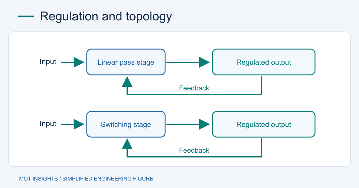
A linear regulator adjusts a pass device to maintain the target. A switching regulator transfers energy in pulses through inductors or a transformer and may control duty cycle, frequency, or pulse grouping. A feedback loop can regulate either approach. A multi-output switching unit can sense one rail directly while another depends on cross-regulation or a downstream regulator. Read the limits for each rail. See how switching supplies control the output.
Use the data sheet to check regulation
| Specification | What it tells you |
|---|---|
| Output accuracy | Distance from nominal under the stated reference conditions or across the stated envelope. |
| Line regulation | Steady output change when input voltage changes with load held at the specified condition. |
| Load regulation | Steady output change when output current changes with input held at the specified condition. |
| Ripple and noise | Repetitive or broadband AC variation under a specified probing method and bandwidth. |
| Transient response | Peak deviation and recovery after a defined input or load step. |
| Minimum load and temperature | Boundaries within which the manufacturer guarantees the other figures. |
A regulated output can show short spikes, ripple or temporary droop. It can also fall out of regulation when the input drops below the required range, a linear stage runs out of headroom or the load exceeds a current limit. The right check depends on whether the load reacts to an average voltage error, a fast disturbance or both. Review the supply’s minimum-load conditions if you need a guarantee at zero output current.
Work through a 12 V load requirement
Suppose a sensor rail accepts 12 V ±3%, which gives a permissible steady interval of 11.64–12.36 V. A supply with a guaranteed combined steady-state output range of 11.8–12.2 V at its terminals leaves 0.16 V of margin at each boundary for other steady errors. If the wiring drops 0.20 V at the highest current, the sensor can see 11.60 V. The supply meets its terminal rating while the installation misses its load requirement.
Use heavier wiring where appropriate, or remote sense if the model supports it and the wiring meets its instructions. Check that the worst-case ripple and a load-step dip are also acceptable at the sensor. Avoid adding individual error terms twice when a manufacturer’s combined accuracy figure already includes them. When the data sheet lists independent limits, construct a worst-case budget with their defined test conditions.
Compare topology only after defining the output
The nominal wattage and a regulated label tell you little about conversion efficiency at your operating point. A linear pass regulator delivering 0.5 A from 15 V to 12 V dissipates roughly 1.5 W in its pass path, excluding quiescent losses. A switch-mode stage may reduce that heat, particularly with a large voltage difference. Its switching ripple and EMI can require additional filtering or layout work. A hybrid design can use a switching stage for bulk conversion followed by a linear regulator for a sensitive rail with enough dropout margin. The linear versus switching supply comparison covers these system tradeoffs.
Measure at the point that matters
On a documented low-voltage setup, hold input fixed and sweep load, then hold load fixed and sweep allowed input. Record the stabilized DC voltage at the supply terminals and at the load. Use a properly rated measurement setup for ripple and load steps and reproduce the supplier’s test conditions when assessing a specification. Our ripple measurement guide explains bandwidth and probe-loop effects.
Use the measured worst case to decide whether you need tighter regulation, better wiring or a different topology. For rectifier or MOSFET selection in a regulated power stage, share the input, output, load and thermal constraints with MOT.