As an application engineer who deals with battery management systems on a perennial basis, whenever I look at a list of BMS plates (such as the 3-4 series of 200A in the chart), I do not focus first on the most visible MMU, but rather on the power of the MOSFET, which carries the role of “safe gate”. Today, we take as an example one of the classic devices that may be used in large quantities — MOT 80N03D — to analyze how an seemingly ordinary MOSFETs becomes the cornerstone of BMS' reliable operation and its deep consideration in BOM's selection.
Device focus: MOT, 80N03D, a balanced 'Guardian '
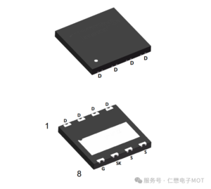
In BMS's discharge-protected circuits, we often see multiple MOSFETs that are used in combination to share large currents. MOT 80N03D is a 30V pressure resistant, 80A current power channel MOSFET, with the core advantage of having a good value for money and a good balance with a reliable roulette.
• Key parameter snapshot:
o Vds = 30V: Perfect coverage of mainstream 3. 7V lithium core 7 applications (approximately 29. 4V full of electricity) with sufficient surplus.
o Id = 80A: A single one can carry a sizeable current, multiple and easily respond to 120A and even higher sustainable discharge needs (as shown in the card model in the chart).
o Rds(on) is typically very low: when Vgs = 10V, its conductivity is only about 1. 8 m. This means that the power consumption and heat in the conductive state is very small and directly increases system efficiency and thermal stability.
: : Excellent sealing: This is usually done using TO-252 (DPAK) seals, which, while providing a good dispersive capacity, take into account PCB ' s plate area and are well suited to BMS ' s limited space application.
In BOM, its role is clear and critical: as an electronic switch, implement the instructions issued by the MMU to securely connect or cut off the main circuit between the battery and the load.
BMS application scenario: Why it?
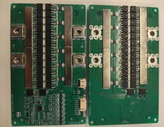
BMS panel in the observation chart, power path is clear: currents flow from a battery link, sampled resistance, then via a row of MOSFET (usually containing charge control and discharge control groups), and eventually to the output end.
1. Respond to steady-state currents: The actual working currents and temperature rises of each device can be easily controlled in a comfortable area for the 120A constant currents, as indicated in the medium model, by combining 3-4 x 80N03D. Its low Rds(on) properties are directly translated here into lower lead losses and higher overall efficiency.
2. Response to instantaneous shocks: electric start-up, load interpolation produces pulse currents that are several times the rated. 80N03D's high-pulse current tolerance ensures that it doesn't overwhelm in these transients and buys time to protect the circuit response.
Simplified driver design: Its modest grid charge allows the common BMS dedicated AFE chip or drive IC to drive directly and efficiently multiple-connected MOSFET, without complex cascade-driven circuits, to simplify BOM and PCB layouts.
From BOM to PCB: Reliability in design details
The layout of the circuit board in the picture is a reflection of how well designed and explains how 80N03D devices are "used":
Symmetrical and UB: We can see the MOSFET is organized. At the bottom of the PCB, their D extremes and S polars are usually connected by large areas of copper. This design ensures a flow of multiple MOSFETs and avoids early failure due to layout asymmetries leading to “excessiveness” of a particular device. This is the key to the ability to combine devices to achieve 120A nominal values.
· Dispersion Design & Thermal Convergence: The sealed metal backboard of the DPAK is welded directly on the large PCB area of copper. This piece of copper is the main radiator. Thermal Via effectively controls the temperature at work by transferring heat to the back or other layers. BOM may also consider the coating of conductor silite or the loading of bulk tablets in this area in response to more demanding conditions.
• Coordination for the protection of circuits: BOM List, near 80N03D, must be accompanied by precision sampling of electrical resistance, fuses, etc. Sampling electrical resistance is used to detect currents in real time, in conjunction with AFE/MCU to protect them; fuses are the last irreversible physical protection. MOSFET, sample electrical resistance, and protection of IC formed a closed-ring protection network on BOM and the electrical road.
Selection Elements and BOM Cost Considerations
When developing BOM, selecting 80N03D devices, engineers weigh:
1. Voltage and current residual: 30V resistance is sufficient for a string of 7 applications, but for a greater number of strings, a higher resistance model is selected. The current capacity needs to be calculated on the basis of peak currents and combined quantities, with at least 30 per cent remaining.
2. Exporting loss and loss and heat budget: Calculates total lead loss and loss under full load P loss = I 2 Rds (on) and ensures that at the expected maximum ambient temperature, MOSFET's temperature does not exceed the safety value (usually 125°C). This determines whether additional heat dispersion measures are necessary.
3. System cost optimization: Although single 80N03D costs are extremely low, they are large in bulk BMS production and the total cost cannot be ignored. It is highly reliable and inefficient to avoid the huge cost of post-sale maintenance, and it is the most economical to choose quality-secure devices over the life cycle.
4. Supply chain security: As a national power semiconductor brand, 80N03D, a generic model such as supply stability, helps to guarantee BOM ' s long-term availability and price stability, which is essential for product production.
Conclusion: small devices, heavy responsibility
A piece of BMS's reliability is hidden in the details of its BOM list and the PCB layout like this. A power like 80N03D, MOSFET, although not a unit price, is stable and reliable as the core execution unit on the current path, which directly determines whether the battery bag is safe “brakes” in each abnormal condition.
For engineers, read BOM is not just about the shape of the component, but about the design intent, the security boundary and the cost considerations behind each component. The choice of a market-tested, parameter-balanced, reliable device like 80N03D is the best balance between performance, cost and risk and a solid basis for building a durable, safe BMS product.