A rectifier diode is a semiconductor device that conducts substantial current in its forward direction and blocks voltage in the reverse direction. Circuits use this one-way behavior to convert alternating current or high-frequency switched waveforms into pulsating DC. Capacitors, inductors, and control circuits then smooth or regulate that energy.
Rectifier diode describes a function and a family of power-rated devices. It includes conventional silicon p-n diodes, fast and ultrafast recovery types, Schottky barrier diodes, and silicon carbide diodes. The best choice depends on input waveform, reverse voltage, current, switching frequency, temperature, efficiency, surge, and cost.
How does a rectifier diode work?
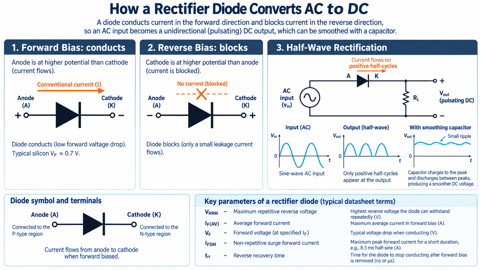
In a silicon p-n diode, the junction forms a depletion region and a built-in electric field. Forward bias lowers the barrier so majority carriers cross the junction and current rises rapidly. Reverse bias widens the depletion region, so only a small leakage current flows until breakdown.
A real forward-biased diode has a voltage drop, so it dissipates approximately Pcond = VF × IF for constant current. With pulsed current, use the waveform and the datasheet forward characteristic at operating temperature. In reverse bias, leakage creates additional loss, especially at high voltage and temperature.
Half-wave and full-wave rectification
Half-wave rectifier
A single diode passes one half of an AC cycle and blocks the other. The circuit is simple but makes poor use of the source and produces large low-frequency ripple. It suits low-power detection, simple chargers, and auxiliary functions more often than efficient power conversion.
Center-tapped full-wave rectifier
Two diodes and a center-tapped transformer alternate conduction so load current flows in the same direction during both input half-cycles. Only one diode drop is in the conducting path, but each diode sees relatively high reverse voltage and the transformer winding is used in halves.
Bridge rectifier
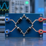
A single-phase bridge uses four diodes. Two conduct on the positive half-cycle and the opposite pair conduct on the negative half-cycle. It uses the full transformer winding without a center tap, although two forward drops appear in series. See how many diodes a bridge rectifier uses for current paths and fault checks.
Important rectifier diode ratings
- VRRM: maximum repetitive peak reverse voltage. Include line tolerance, ringing, transformer leakage, load transients, and derating.
- IF(AV): average forward current under stated waveform, lead, case, or ambient conditions. It is not an unlimited current allowance.
- IF(RMS): RMS current relevant to conduction heating in leads, packages, and wiring.
- IFSM: nonrepetitive surge current for a defined waveform and initial junction temperature. Charging a large capacitor can approach this limit.
- VF: forward voltage at specified current and temperature. It drives conduction loss.
- IR: reverse leakage, which usually increases strongly with junction temperature.
- trr and Qrr: reverse-recovery time and charge for p-n diodes. They influence commutation loss, current spikes, and EMI.
- Tj and thermal resistance: junction-temperature limit and heat-flow path through the package, PCB, or heatsink.
Standard, fast, Schottky, or SiC?
Standard silicon rectifier
A standard-recovery p-n diode is economical and robust for 50/60 Hz mains rectification. Its stored charge can be too large for high-frequency converters, where reverse recovery raises switch loss and ringing.
Fast and ultrafast silicon diode
These p-n devices reduce recovery time and charge for switch-mode circuits. Designers must examine the recovery current shape as well as the headline time because abrupt recovery can excite parasitic inductance and produce EMI.
Schottky diode
A Schottky barrier diode has low forward voltage and negligible minority-carrier recovery. It is attractive for low-voltage, high-current outputs, but reverse leakage is higher and voltage capability is often lower than silicon p-n alternatives. The guide to Schottky diode operation and selection explains those trade-offs.
Silicon carbide Schottky diode
A SiC Schottky diode combines high reverse-voltage capability with essentially no minority-carrier reverse recovery. It can reduce switching loss in power-factor correction and high-voltage converters, although forward drop, capacitance, cost, and package layout still require evaluation.
Why reverse recovery matters
Forward current stores charge in a silicon p-n junction. When the circuit suddenly applies reverse voltage, current continues briefly while that charge is removed. The reverse current adds stress to the commutating switch and the diode, and loop inductance converts rapid current change into voltage overshoot.
Reverse recovery depends on forward current, current slew rate, junction temperature, and the circuit. A datasheet value measured under one condition cannot be copied blindly into another design. Use realistic double-pulse measurements or a validated device model for demanding converters.
Capacitor-input rectifier current is not sinusoidal
After a bridge rectifier, a large reservoir capacitor charges near the peaks of the AC waveform. The average load current may look modest, but diode current arrives in narrow, high-amplitude pulses. Those pulses raise RMS heating, transformer copper loss, harmonic current, and inrush stress.
When the supply is first connected, an empty capacitor can resemble a short circuit. Source impedance, an NTC limiter, a resistor-plus-relay circuit, or active inrush control may be required. Verify the diode’s surge rating at the actual starting temperature and pulse repetition.
Thermal design and failure modes
Estimate conduction loss over the complete waveform and add reverse-recovery and leakage loss where relevant. Convert loss to junction temperature using the correct package thermal path. PCB copper and airflow can dominate small surface-mount packages, while stud, tab, and module rectifiers may use a heatsink.
Repeated excessive temperature can increase leakage, degrade solder, and shorten component life. Schottky leakage can create a reinforcing loop: higher temperature increases leakage, which creates more heat. The article on preventing Schottky thermal runaway shows how to test that risk.
Common failure causes include reverse-voltage overshoot, inrush beyond IFSM, inadequate cooling, wrong recovery speed, an output short, poor solder joints, and excessive mechanical stress. A shorted diode may blow a fuse or transformer winding; an open diode can produce low output, severe ripple, or half-wave operation.
How to select a rectifier diode
- Define the maximum repetitive and transient reverse voltage across each diode.
- Calculate average, RMS, peak, and surge forward current from the actual waveform.
- Estimate forward-conduction loss at hot operating conditions.
- For switching circuits, evaluate reverse recovery, capacitance, and commutation behavior.
- Check leakage at maximum reverse voltage and junction temperature.
- Calculate junction temperature with the real PCB, interface, heatsink, and airflow.
- Confirm creepage, package isolation, mounting, and safety requirements.
- Measure current, voltage overshoot, temperature, efficiency, and EMI on hardware.
Rectification is also a major loss mechanism in switching converters. At low output voltage, synchronous MOSFETs can replace diodes, but their timing must prevent shoot-through and excessive body-diode conduction. See synchronous-rectifier dead-time optimization.
Frequently asked questions
Is every diode a rectifier diode?
Many diodes can rectify small signals, but rectifier diodes are designed and rated for power conversion. Signal, Zener, photodiode, and RF devices have different optimized functions.
Does a rectifier convert AC into perfectly smooth DC?
No. The diode network produces pulsating DC. A capacitor or LC filter reduces ripple, and a regulator may be needed for a stable output.
Can I replace a standard diode with a faster one?
Sometimes, but confirm voltage, current, surge, forward loss, leakage, package, pinout, thermal performance, and recovery behavior. A faster but more abrupt diode can increase ringing without layout or snubber changes.
Why are two diode drops present in a bridge?
Current crosses one diode from the AC source into the positive output and another from the negative output back to the source. The conducting pair changes every half-cycle.