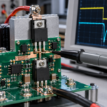
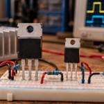
What is a MOSFET? A metal-oxide-semiconductor field-effect transistor is a semiconductor device that uses voltage at an insulated gate to control current between two other terminals, the drain and source. In digital electronics, tiny MOSFETs build logic gates and memory. In power electronics, larger MOSFETs switch energy in converters, motor drives, chargers, battery systems, and load-control circuits.
The most useful mental model is a voltage-controlled current path. The gate does not normally carry continuous control current. Instead, a driver charges and discharges the gate capacitance. The resulting electric field creates or removes a conductive channel inside the silicon.
What does MOSFET stand for?
MOSFET stands for metal-oxide-semiconductor field-effect transistor. Early devices used a metal gate over a silicon-dioxide insulating layer. Modern processes may use polysilicon gates, high-k dielectrics, trench structures, superjunction structures, or other materials, but the familiar name remains.
The term field effect describes the operating principle: an electric field changes the conductivity of the channel. Because the gate is insulated, its steady-state input resistance is extremely high. Real gates still have leakage, capacitance, and maximum voltage limits, so they cannot be treated as perfect open circuits.
The terminals of a MOSFET
A discrete power MOSFET is usually described by three accessible terminals:
- Gate: the control terminal. Gate-to-source voltage determines whether the channel is off, partly conducting, or strongly enhanced.
- Drain: one end of the controlled current path.
- Source: the reference terminal for gate drive and the other end of the controlled current path.
A fourth terminal, the body or substrate, exists physically. In most discrete power MOSFETs it is internally connected to the source. That connection creates the intrinsic body diode shown in many circuit symbols and datasheets.
How a MOSFET works in simple terms
Consider a common enhancement-mode N-channel MOSFET. With gate-to-source voltage, VGS, near zero, the drain-to-source path is off except for leakage. Raising VGS above the threshold begins to form a channel. Increasing the gate voltage further strengthens the channel and reduces its resistance.
When a suitable gate voltage fully enhances a power MOSFET, the device behaves approximately like a small resistance called RDS(on). Conduction loss can be estimated as I2R for a steady current. When the gate voltage is removed, the channel disappears and the device blocks drain-to-source voltage up to its rated limits.
Threshold voltage is not the full-on voltage. Datasheets usually measure VGS(th) at a very small drain current. A MOSFET may start conducting at that value yet still dissipate excessive power at the application’s load current. Designers should use the RDS(on) specifications and curves at the actual gate-drive voltage.
Main MOSFET types
N-channel and P-channel MOSFETs
N-channel MOSFETs use electrons as the main charge carriers and generally achieve lower RDS(on) for a given die size and voltage class. They dominate efficient power conversion. P-channel MOSFETs use holes as the main carriers. They usually have higher resistance but can simplify high-side switching at modest current and voltage.
Enhancement mode and depletion mode
An enhancement-mode MOSFET is normally off at VGS = 0 V and turns on when the gate is driven with the correct polarity. Most discrete power MOSFETs are enhancement-mode devices. A depletion-mode MOSFET is normally on and requires an opposing gate voltage to reduce channel current. Depletion devices serve specialized biasing, current-source, startup, and protection functions.
Signal MOSFETs and power MOSFETs
Small-signal MOSFETs handle low currents in analog switching, level shifting, and amplification. Power MOSFETs use large cell arrays and vertical structures to handle higher current and voltage. Their packages and datasheets emphasize conduction loss, switching charge, thermal resistance, avalanche capability, and body-diode behavior.
MOSFET operating regions
| Region | Electrical condition | Typical use |
|---|---|---|
| Cutoff | The channel is not sufficiently enhanced | Open switch or off state |
| Ohmic or linear | The channel behaves mainly as a controlled resistance | Power-switch on state, analog switch, electronic load |
| Saturation | Drain current is controlled mainly by gate overdrive | Amplifiers and current sources |
MOSFET terminology can confuse designers familiar with bipolar transistors. A fully on power MOSFET normally operates in the ohmic region, not in the MOSFET saturation region. Linear operation is possible, but safe operating area and thermal stability must be checked carefully.
Important MOSFET specifications
| Parameter | What it means | Why it matters |
|---|---|---|
| VDSS | Maximum drain-to-source blocking voltage | Must exceed the worst-case bus voltage and transients with suitable margin |
| ID | Rated drain current under stated thermal conditions | Package, PCB, and temperature often limit usable current before the headline rating |
| RDS(on) | On-state resistance at a specified VGS and temperature | Sets a major part of conduction loss |
| Qg | Total gate charge | Affects driver current, transition time, and gate-drive loss |
| Coss and Eoss | Output capacitance and stored energy | Can dominate loss in hard-switched or resonant circuits |
| Qrr | Body-diode reverse-recovery charge | Affects commutation loss, voltage overshoot, and EMI |
| Rth | Thermal resistance through the package and mounting path | Connects power loss to junction temperature |
What are MOSFETs used for?
- Switching in buck, boost, flyback, LLC, PFC, and synchronous rectifier stages
- Motor phase control, solenoid drive, and pulse-width modulation
- Battery protection, reverse-polarity protection, and electronic fuses
- Load switches, power-path controllers, and hot-swap circuits
- Analog amplifiers, current sources, and voltage-controlled resistors
- Digital logic, processors, memory, sensors, and mixed-signal integrated circuits
How to choose a MOSFET
- Define voltage stress. Include input tolerance, inductive overshoot, ringing, and abnormal conditions, then select a suitable VDSS margin.
- Calculate current and conduction loss. Use RDS(on) at the expected junction temperature and available gate voltage, not only the 25 °C headline value.
- Estimate switching loss. Consider Qg, Qgd, Coss, Eoss, switching frequency, driver strength, and commutation conditions.
- Check thermal performance. Model the complete path from junction through package, PCB copper, interface material, and heatsink to ambient.
- Validate dynamic limits. Review safe operating area, avalanche energy, body-diode behavior, and repetitive transient ratings.
- Measure the prototype. Confirm gate voltage, drain overshoot, switching energy, case temperature, and EMI under worst-case operating conditions.
Common MOSFET mistakes
Frequent errors include driving a non-logic-level MOSFET directly from a low-voltage microcontroller, using VGS(th) as the required gate voltage, ignoring the rise of RDS(on) with temperature, and selecting only the lowest resistance device without considering gate charge or output capacitance. Poor PCB layout can also create gate ringing and excessive drain overshoot even when the component ratings look adequate.
Frequently asked questions
Is a MOSFET controlled by voltage or current?
A MOSFET is controlled primarily by gate-to-source voltage. Current is still required during switching to charge and discharge the gate capacitances. Faster transitions require more peak gate current.
Does a MOSFET conduct in both directions?
An enhanced MOSFET channel can conduct current in either direction, although ratings and measurement conventions matter. A single power MOSFET’s body diode conducts in only one direction when the channel is off, so two back-to-back MOSFETs are often used for bidirectional blocking.
Can a MOSFET amplify a signal?
Yes. Biasing a MOSFET in its saturation region allows a small gate-voltage change to control drain current. Power MOSFETs can also operate linearly, but safe operating area and heat dissipation may be more restrictive than their switching ratings suggest.
Summary
A MOSFET is an insulated-gate, voltage-controlled transistor used to switch or regulate current. Understanding its terminals and operating regions explains the basic device. Reliable design then depends on comparing voltage, current, resistance, charge, capacitance, thermal behavior, and transient limits at the application’s real operating point.