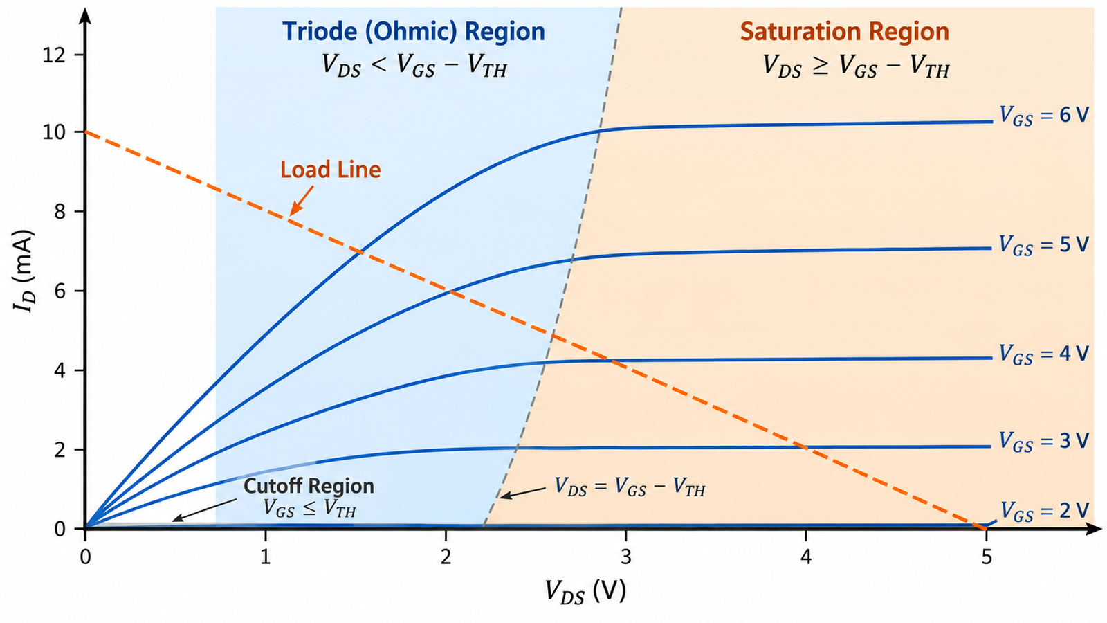
To check a MOSFET’s operating region, find its instantaneous VGS and VDS, compare VGS with threshold, and compare VDS with the gate overdrive VGS − VTH. In the basic long-channel N-MOS enhancement model: below threshold is cutoff; 0 ≤ VDS < VGS − VTH is triode; and VDS ≥ VGS − VTH is saturation.
Those boundaries are excellent for learning and first-order analog analysis, but real power MOSFET switching requires data-sheet curves, device models, parasitics, and temperature.
Measure voltages with the correct reference
VGS is gate voltage relative to the MOSFET source, not ground. VDS is drain relative to source. In a high-side switch or switching bridge, the source moves rapidly, so two ground-referenced scope channels can produce an unsafe or wrong result. Use an appropriately rated differential probe or isolated measurement method.
Polarity changes for P-channel devices; writing the terminal voltages explicitly prevents sign mistakes.
Identify cutoff
If VGS is below the applicable threshold, the inversion channel is not strongly formed and the ideal model calls the device off. Real devices still have subthreshold current, leakage, capacitance current, and a body-diode path. Threshold is a range specified at a small test current and changes with temperature.
Review how a MOSFET channel forms before using threshold as a switching-drive specification.
Identify triode or ohmic operation
When VGS is above threshold and VDS is lower than gate overdrive in the simple model, the device is in triode, also called ohmic or linear region. A fully enhanced power switch normally operates at a low VDS here and is conveniently modeled by RDS(on).
Terminology can confuse: power engineers may call a pass transistor “linear-mode” operation even while discussing a different part of the textbook curve. State the actual voltages and dissipation.
Identify saturation
When VDS reaches or exceeds the gate overdrive boundary, the channel pinches near the drain in the ideal model and current depends mainly on gate voltage. This saturation region is useful for analog gain and current-source behavior. It is not the same as BJT saturation, which describes a strongly on, low-voltage state.
Channel-length modulation gives the saturation curve a finite slope, and short-channel devices require more advanced models.
Follow a switching trajectory
A power MOSFET moves through regions during every edge. Before turn-on it blocks high VDS; during the Miller interval it carries current while drain voltage falls; when fully on it reaches low-voltage ohmic operation. Turn-off reverses the path. Gate resistance, load type, diode recovery, and circuit inductance set how long it remains in high-dissipation states.
The gate-resistor tuning guide relates that trajectory to switching loss and EMI.
Check SOA and heat after naming the region
Knowing the region does not prove safe operation. Calculate instantaneous and average power VDSID, consult DC or pulsed SOA, and account for junction temperature and transient thermal impedance. Linear-mode hotspots can arise from current crowding, especially in devices optimized for switching.
For a load line or current limiter, plot the complete voltage-current path and duration rather than checking only the final bias point.
Turn the answer into a robust MOSFET design
For How to Check Which Region a MOSFET Is Operating In, create an operating-state table before choosing a device or protection value. Include off, startup, steady on, PWM transitions, shutdown, reverse current, load connection, controller reset, brownout, open load, overload, and short circuit. For each state, write the expected VGS, VDS, current, duration, repetition, and starting temperature. This exposes short but severe events that an average-current calculation hides.
Next, compare the table with guaranteed data-sheet limits and characterized curves. Use voltage margin for supply tolerance and ringing; use RDS(on) at the actual gate voltage and hot junction; use total gate charge and Miller charge for driver sizing; and use DC or pulsed SOA for intervals where voltage and current coexist. Include package, PCB copper, interface material, airflow, connector, and source-return inductance in the model. A transistor cannot be evaluated separately from its commutation path and gate loop.
Build a staged test plan that begins with limited available energy. Capture gate-to-source voltage at the pins, drain-source voltage, current, and temperature while changing one stress at a time. Repeat enough cycles to reveal cumulative heating and recovery behavior. Define pass limits before looking at the waveform, preserve oscilloscope files, and record device lot, ambient, probe method, and firmware revision. If measured peaks approach an absolute maximum, redesign for margin rather than accepting the result because one prototype survived.
Practical validation checklist
Validate at the worst credible supply voltage, load current, switching frequency, ambient temperature, and fault condition. Measure gate-to-source voltage at the device pins, drain-to-source voltage with adequate bandwidth, current, case temperature, and—when power or pulses are significant—estimated junction temperature. Account for probe ground inductance and avoid interpreting ringing created by the measurement setup as circuit behavior.
Compare every result with the data-sheet safe operating area, absolute maximum ratings, transient thermal impedance, and temperature-dependent curves. Test startup, shutdown, load connection, stalled or shorted load, controller brownout, and repeated operation. The guides to reading MOSFET safe operating area and MOSFET thermal calculation provide useful companion checks.
Frequently asked questions
Is MOSFET saturation the fully on state?
No. In MOS terminology saturation is the current-source-like region; a fully on power switch is normally in the low-VDS ohmic region.
Can I use VGS(th) to decide whether a MOSFET is on?
It identifies channel onset at a small test current, not the gate voltage required for low RDS(on).
What region is a MOSFET in during switching?
It traverses cutoff, high-dissipation transition regions, and low-VDS ohmic operation over each edge.
Do these equations work for every MOSFET?
They are first-order rules. Modern compact models and data-sheet curves are needed for precise short-channel or power-device behavior.