How many diodes are used in a bridge rectifier? A standard single-phase full-wave bridge rectifier uses four diodes. The diodes are arranged so that two conduct during the positive half-cycle and the other two conduct during the negative half-cycle. Current therefore passes through the load in the same direction on both halves of the AC waveform.
This four-diode answer applies to the familiar single-phase bridge used at the input of adapters, chargers, offline converters, and many other power-supply systems. Other rectifier arrangements use different diode counts, so the source and topology must be identified before selecting parts.
Why a bridge rectifier needs four diodes
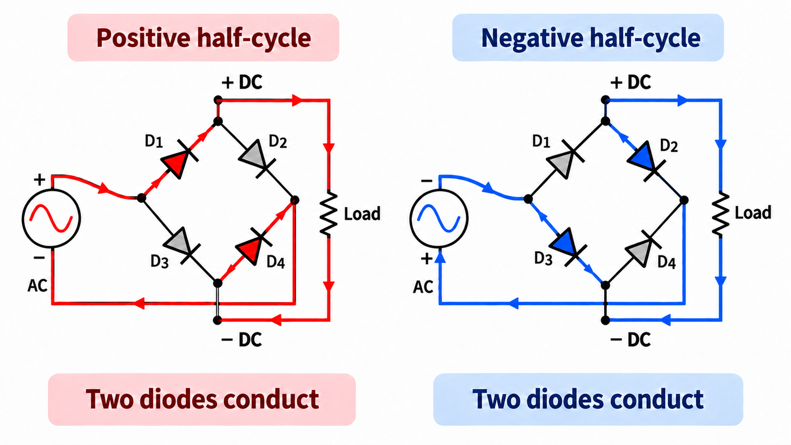
An AC source reverses polarity every half-cycle. A DC load needs a fixed positive and negative terminal. The bridge acts as an automatic steering network: whichever AC terminal is positive is connected to the positive DC output through one diode, while the return current reaches the negative AC terminal through a second diode.
The remaining two diodes are reverse-biased for that half-cycle. When the source polarity reverses, the conducting and blocking pairs exchange roles. The bridge therefore produces full-wave rectification without requiring a center-tapped transformer.
Which diodes conduct on each half-cycle?
Label the bridge diodes D1 through D4. On the positive half-cycle, current might flow from the positive AC terminal through D1, through the load, and back through D4. On the negative half-cycle, the other AC terminal becomes positive, so current flows through D2, through the load in the same direction, and returns through D3.
| AC condition | Conducting diodes | Load-current direction |
|---|---|---|
| First half-cycle | D1 and D4 | Positive DC terminal to negative DC terminal |
| Second half-cycle | D2 and D3 | Positive DC terminal to negative DC terminal |
Component labels depend on the schematic, but the rule does not change: one diode connects the momentarily positive AC terminal to the positive DC node, and another connects the negative DC node to the momentarily negative AC terminal.
Four installed, two conducting at a time
The distinction between installed diodes and conducting diodes matters. A bridge contains four diodes, but normal load current passes through only two at any instant. Those two forward voltage drops appear in series.
For a rough estimate, the instantaneous bridge loss during conduction is approximately 2 × VF × I. If each diode drops 0.8 V at 2 A, the conducting path dissipates about 3.2 W at that operating point. Real calculations must use the diode voltage at the actual current and junction temperature. A capacitor-input supply also draws narrow charging pulses, so RMS current and thermal stress may be much higher than the average DC load current suggests.
How the output waveform changes
A bridge flips the negative half-cycle upward. With a 50 Hz input, the rectified waveform has peaks at 100 Hz; with a 60 Hz input, it has peaks at 120 Hz. The output is pulsating DC rather than smooth DC.
A reservoir capacitor can charge near each voltage peak and supply the load between peaks. The capacitor reduces ripple but increases diode peak and RMS current. In higher-power converters, designers may add power-factor correction, controlled rectification, or a different front-end architecture.
Bridge rectifier versus other rectifier circuits
| Rectifier type | Typical diode count | Main characteristic |
|---|---|---|
| Half-wave, single phase | 1 | Uses one half of the AC cycle |
| Full-wave, center-tapped | 2 | Requires a center-tapped transformer secondary |
| Full-wave bridge, single phase | 4 | Uses the full secondary without a center tap |
| Three-phase six-pulse bridge | 6 | Three upper and three lower rectifying devices |
A synchronous bridge can replace some or all diodes with controlled MOSFETs to reduce conduction loss. The switching and control are more complex, so the four-diode bridge remains attractive when simplicity, cost, and robustness matter more than the last fraction of efficiency.
How to select the four rectifier diodes
Reverse-voltage rating
Each diode must block the worst-case reverse voltage, including line tolerance, transformer regulation, ringing, and transients. Use repetitive peak reverse voltage or the equivalent datasheet rating, not the nominal RMS input alone.
Average and RMS current
Check the average forward-current rating, but do not stop there. Capacitor charging pulses can create substantial RMS heating. Confirm the current waveform, package thermal resistance, copper area, ambient temperature, and cooling conditions.
Surge-current capability
At startup, an empty bulk capacitor can draw a large inrush pulse. The non-repetitive surge rating must be coordinated with source impedance, fusing, inrush limiting, and capacitor size.
Forward voltage and temperature
Lower forward voltage reduces conduction loss, but leakage normally rises with temperature in some device families. This trade-off is especially important in Schottky designs. The article on preventing thermal runaway in Schottky rectifiers explains why electrical and thermal behavior must be evaluated together.
Reverse recovery
At mains frequency, standard rectifiers may be adequate. At high switching frequency, reverse-recovery charge can increase loss, voltage overshoot, and EMI. Review the commutation conditions rather than selecting by current rating alone. For a deeper treatment, see reverse-recovery losses in fast rectifiers.
Discrete diodes or an integrated bridge package?
The four devices can be individual diodes or a single bridge module containing all four junctions. An integrated bridge simplifies assembly and normally marks two AC pins plus positive and negative DC pins. Discrete parts give more freedom to select package, thermal layout, and diode technology.
Always verify the package pinout. The physical order of AC, positive, and negative terminals varies among packages. A wiring error can short the source or reverse the DC output.
Common design mistakes
- Counting only the two conducting diodes and saying that a bridge contains two diodes.
- Using RMS input voltage as the diode’s reverse-voltage requirement without considering the peak and transients.
- Rating current from the DC load average while ignoring capacitor charging pulses.
- Calculating only one forward drop even though two diodes are in the current path.
- Ignoring startup surge current into the bulk capacitor.
- Using a slow diode in a high-frequency commutation path.
- Providing too little copper or airflow for the bridge’s combined loss.
Frequently asked questions
Can a bridge rectifier work with three diodes?
A conventional single-phase full-wave bridge needs four functioning diodes. If one diode is open, one half-cycle is lost. If one diode is shorted, the source may be shorted through another diode during part of the cycle. Neither condition is normal full-wave operation.
Why are only two diodes on at once?
The source polarity forward-biases one route through the bridge and reverse-biases the other. The active route contains one diode on the way to the positive output and one on the return path.
Does a bridge rectifier output pure DC?
No. It produces full-wave pulsating DC. A capacitor, inductor, regulator, or switching stage is normally used when the load requires lower ripple or regulated voltage.
Are bridge diodes the same as flywheel diodes?
They perform different circuit roles. A bridge steers alternating input current. A freewheeling diode provides a path for inductive load current when a switch turns off. The selection considerations in freewheeling diode design for motor drives reflect that different stress.
Summary
A standard single-phase full-wave bridge rectifier uses four diodes. Two conduct on each half-cycle, so the load sees one polarity while the active pair alternates. A sound design then checks the two-diode conduction loss, reverse-voltage margin, RMS and surge current, recovery behavior, package temperature, and the effect of any reservoir capacitor.