MOSFET threshold voltage is not a single directly observed physical point; it is a value extracted from measured or simulated characteristics using a stated rule. Constant-current, linear-extrapolation, transconductance, derivative, ratio, integral, and nonlinear fitting methods can return different answers from the same transistor. That does not automatically make one wrong—the methods emphasize different regions and purposes.
A useful threshold report therefore includes the method, drain voltage, substrate bias, temperature, sweep direction and rate, device geometry, current normalization, series-resistance treatment, and instrument resolution. Comparisons without that metadata can mistake a procedural shift for a device shift.
What threshold voltage represents
In a textbook long-channel MOSFET, threshold marks the gate bias associated with strong inversion under a particular definition. Real devices transition gradually from subthreshold to above-threshold conduction. Mobility degradation, short-channel effects, drain-induced barrier lowering, interface traps, body bias, quantum effects, and series resistance blur a unique boundary.
Power-MOSFET data sheets often specify VGS(th) at a small drain current. It confirms a test criterion, not the gate voltage for low RDS(on). Read how a MOSFET transistor works before applying threshold values to switching design.
Constant-current extraction
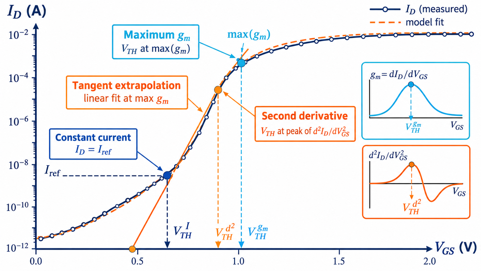
The constant-current method defines VTH as the gate voltage at which drain current reaches a chosen criterion, often normalized by width-to-length ratio. It is simple, repeatable, and easy to automate. It can work across broad device types if the current definition is clearly documented.
Its result depends directly on the selected current, drain bias, geometry normalization, leakage floor, and temperature. Two laboratories using different current criteria can report different thresholds from identical data. For power devices with proprietary cell geometry, normalization also needs care.
Linear extrapolation in the linear region
Linear-extrapolation methods use the approximately linear portion of ID versus VGS at low drain voltage and extrapolate a tangent or fitted line toward the gate axis. A common variant chooses the maximum transconductance point and applies a correction related to drain voltage.
The method is intuitive but sensitive to mobility degradation, source/drain resistance, the selected fitting window, and numerical smoothing. It should not be applied to a visibly curved region simply because software can draw a line.
Transconductance and derivative methods
Transconductance gm is the derivative of drain current with respect to gate voltage. Methods may use the maximum gm, an extrapolation around it, the second derivative of current, or derivatives of related functions. Peaks can provide objective landmarks and help separate regimes.
Differentiation amplifies noise and step-size artifacts. Filtering can move the peak and must be disclosed. Contact resistance, trap dynamics, hysteresis, and instrument compliance can distort derivatives. Repeat the extraction with several smoothing windows and sweep steps to assess robustness.
Ratio, integral, and model-fitting approaches
Ratio methods transform current and transconductance to reduce sensitivity to some mobility terms. Integral methods use an area under the transfer curve and may be less noise sensitive than high-order derivatives. Nonlinear optimization fits a device equation or compact model to a chosen data region and extracts threshold with other parameters.
Model fitting is powerful when the model is valid and identifiable, but correlations between mobility, series resistance, body factor, and threshold can hide uncertainty. Report parameter bounds, residuals, fit window, and whether one parameter set explains multiple drain biases and temperatures.
Select the method for the purpose
Process control favors a stable automated metric correlated with manufacturing. Reliability studies need sensitivity to oxide charge, interface traps, bias-temperature instability, or radiation while controlling recovery during measurement. Compact-model extraction needs internal consistency across operating regions. Circuit design may care more about current at a specified gate voltage than an abstract threshold.
For depletion-mode devices, the sign and sweep range require special care; see testing depletion-mode MOSFETs. For gate reliability, distinguish threshold shift from oxide breakdown discussed in gate-oxide voltage limits.
Engineering checklist
Preserve raw I–V data and automate extraction with version-controlled settings. Measure forward and reverse sweeps, several drain biases, temperatures, and replicate devices. Log settling time, integration time, compliance, preconditioning, and delay after electrical stress. Plot the extracted point or fitted line on the raw curve so reviewers can see whether the method is behaving sensibly.
Run a sensitivity study before freezing the method. Vary the current criterion, fit window, smoothing strength, sweep increment, and drain bias within reasonable bounds. If a small procedural change produces a large threshold shift, the reported uncertainty should reflect it. Cross-check one method from each family when characterizing an unfamiliar technology.
Do not compare a data-sheet constant-current threshold directly with a research paper’s extrapolated or derivative threshold. When tracking aging, keep the method and measurement delay identical because recovery can occur during the test. Report central value, spread, repeatability, and sensitivity to sweep step or smoothing. A method is strongest when it is physically defensible, numerically stable, and aligned with the decision the threshold value must support.
Frequently asked questions
Which threshold extraction method is best?
There is no universal best method. Choose one suited to the device, data quality, and purpose, then document and apply it consistently.
Why is data-sheet VGS(th) so low?
It is usually measured at a small specified current and does not indicate the voltage needed for low on-resistance at load current.
Does drain voltage change extracted threshold?
Yes. Drain-induced barrier lowering, the chosen operating regime, and method corrections can make the extracted value drain-bias dependent.
Why do derivative methods look noisy?
Numerical differentiation amplifies measurement noise and quantization; sweep step and filtering strongly affect the result.