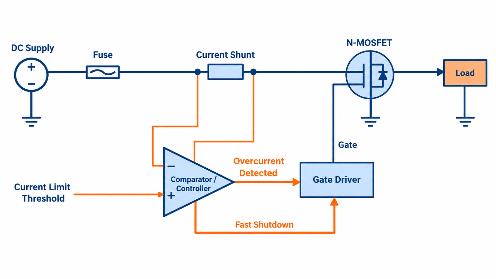
Protect a MOSFET from overcurrent by detecting excessive current quickly, controlling or removing gate drive, and limiting the total energy delivered into the fault. A fuse alone is rarely fast enough to protect the silicon from a hard short. Conversely, a fast comparator alone may not protect wiring or isolate a failed-short transistor.
The design must distinguish normal inrush and load transients from overload, stall, and short circuit. It also needs a safe recovery policy because repeated retries can accumulate more heat than one event.
Define the overcurrent cases
List steady overload, output short, motor stall, transformer saturation, capacitor inrush, shoot-through, and reverse current separately. Record peak current, bus voltage, expected duration, repetition, and starting junction temperature. A MOSFET that tolerates high current at low VDS may fail rapidly when a short forces high current and high voltage together.
Use the MOSFET safe operating area rather than the headline continuous-current rating.
Choose a sensing method
A low-side shunt is simple and accurate but introduces ground offset. A high-side shunt preserves ground and needs a suitable common-mode amplifier. Current transformers and Rogowski methods suit changing current, while integrated smart switches may include calibrated sensing. RDS(on) sensing reduces parts but changes strongly with temperature and device tolerance.
Place the sense path to avoid gate-drive and load-return currents corrupting the signal. Kelvin connections are important at milliohm levels.
Respond on the right time scale
A fast comparator can terminate a switching pulse before the device exceeds its peak limit. Slower firmware can supervise average current and user policy, but it should not be the only protection against microsecond faults. Add blanking only long enough to ignore known switching spikes; excessive blanking creates an unprotected window.
Gate turn-off must be controlled. An abrupt current interruption through stray or load inductance can create a drain-voltage spike, so coordinate current protection with clamping.
Decide between limiting and shutdown
Linear current limiting keeps the MOSFET partially on, which can create a concentrated hotspot and exceed DC SOA even when total power appears reasonable. A switching current limit or quick latch-off often reduces stress. Hot-swap and e-fuse designs use specially selected devices, timers, foldback, and thermal monitoring to manage linear operation.
Hiccup restart reduces average fault power but must allow adequate cooling and avoid endlessly actuating a damaged load.
Coordinate the fuse and upstream source
Select a fuse or breaker from cable ampacity, connector limits, normal surge, available fault current, interrupt rating, and time-current curve. Ensure the upstream source cannot sustain a dangerous arc or PCB fault after the electronic control fails. A current-limited bench supply can mask behavior that will be severe on a low-impedance battery.
The wider MOSFET protection strategy shows how drain, gate, current, and thermal safeguards work together.
Test fault energy, not just trip current
Capture current and VDS from fault inception through shutdown and calculate the energy deposited in the MOSFET. Repeat at high bus voltage, hot junction, minimum gate drive, and maximum wiring inductance. Test a fault applied before startup as well as during normal operation.
Confirm that loss of sensor power, an open shunt connection, stuck controller, or failed MOSFET produces a defined safe response. Protection should not depend on one unmonitored signal.
Turn the answer into a robust MOSFET design
For How to Protect a MOSFET From Overcurrent, create an operating-state table before choosing a device or protection value. Include off, startup, steady on, PWM transitions, shutdown, reverse current, load connection, controller reset, brownout, open load, overload, and short circuit. For each state, write the expected VGS, VDS, current, duration, repetition, and starting temperature. This exposes short but severe events that an average-current calculation hides.
Next, compare the table with guaranteed data-sheet limits and characterized curves. Use voltage margin for supply tolerance and ringing; use RDS(on) at the actual gate voltage and hot junction; use total gate charge and Miller charge for driver sizing; and use DC or pulsed SOA for intervals where voltage and current coexist. Include package, PCB copper, interface material, airflow, connector, and source-return inductance in the model. A transistor cannot be evaluated separately from its commutation path and gate loop.
Build a staged test plan that begins with limited available energy. Capture gate-to-source voltage at the pins, drain-source voltage, current, and temperature while changing one stress at a time. Repeat enough cycles to reveal cumulative heating and recovery behavior. Define pass limits before looking at the waveform, preserve oscilloscope files, and record device lot, ambient, probe method, and firmware revision. If measured peaks approach an absolute maximum, redesign for margin rather than accepting the result because one prototype survived.
Practical validation checklist
Validate at the worst credible supply voltage, load current, switching frequency, ambient temperature, and fault condition. Measure gate-to-source voltage at the device pins, drain-to-source voltage with adequate bandwidth, current, case temperature, and—when power or pulses are significant—estimated junction temperature. Account for probe ground inductance and avoid interpreting ringing created by the measurement setup as circuit behavior.
Compare every result with the data-sheet safe operating area, absolute maximum ratings, transient thermal impedance, and temperature-dependent curves. Test startup, shutdown, load connection, stalled or shorted load, controller brownout, and repeated operation. The guides to reading MOSFET safe operating area and MOSFET thermal calculation provide useful companion checks.
Frequently asked questions
Can a current-limiting power supply protect the MOSFET?
It can reduce available energy, but production protection must be designed for the actual source, wiring, and fault response.
Why does the MOSFET fail before the fuse opens?
Semiconductor thermal time constants can be microseconds or milliseconds, while a fuse may need much longer at the available fault current.
Is RDS(on) sensing accurate?
It can be useful, but resistance varies with temperature, gate drive, device spread, and aging, so thresholds need margin or calibration.
Should protection retry automatically?
Only if repeated attempts are safe for the MOSFET, load, wiring, and application; otherwise use limited retries or latch-off.