It is reasonable to expect modern compact PLC power modules to use switched conversion internally, but you should not treat every CompactLogix power supply as one documented switch-mode design. CompactLogix covers multiple generations and catalog numbers. Public installation and technical data focus on input ratings, backplane output capacity, mounting, dissipation, isolation, and environmental limits rather than publishing a complete internal schematic.
For engineering, maintenance, or replacement, use the exact catalog number and revision. Do not infer interchangeability from the general phrase “switch-mode power supply.”
Identify the exact module
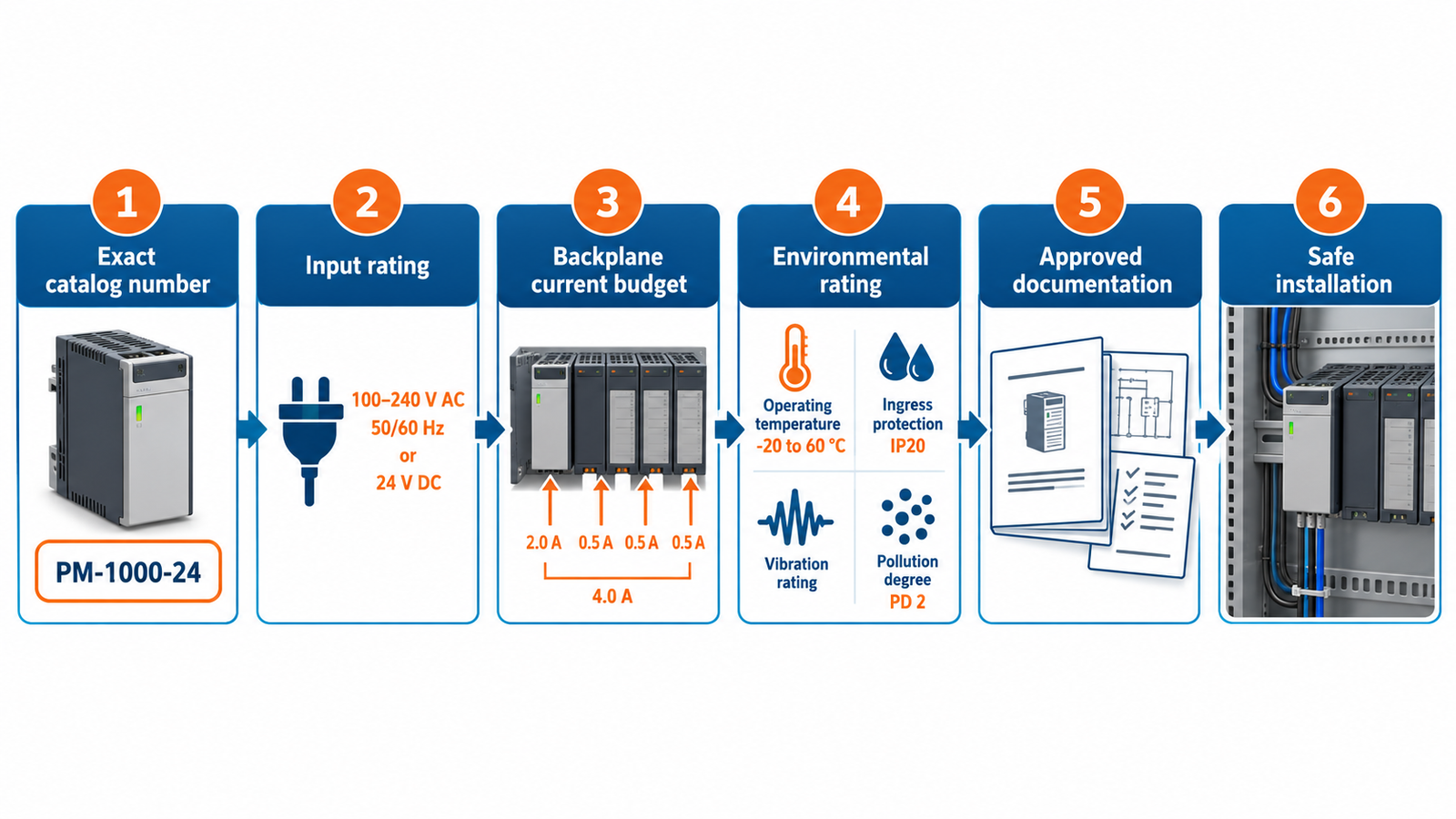
Read the side label, controller family, catalog number, series, and revision. A 1769 power supply, an embedded CompactLogix supply, and a newer platform module can have different input voltages, backplane limits, placement rules, and certifications. Record the surrounding I/O load and expansion-bank arrangement.
Obtain the official Rockwell installation instructions and technical data for that identifier rather than a reseller summary.
Use published ratings as the decision basis
Check nominal and allowed input range, frequency, inrush, output capacity at required backplane voltages, maximum distance rating, isolation, power dissipation, wire size, terminal torque, enclosure type, ambient temperature, altitude, and pollution degree. These parameters determine whether the module is safe and compatible regardless of its internal topology.
General switching-power-supply principles can explain likely behavior but cannot replace product documentation.
Why topology is not enough
Two supplies can both use high-frequency switching yet differ in isolation, grounding, output sequencing, current limiting, hold-up, conducted emissions, diagnostics, and backplane signaling. An ordinary DIN-rail 24 V supply is not automatically a substitute for a dedicated controller backplane module.
Likewise, knowing that a converter switches does not reveal field-repair procedures or authorize component-level service.
Plan the power budget
Sum the required backplane current for the controller and every I/O, communication, and specialty module on each rail. Apply placement and expansion-bank rules, then add design margin without exceeding the manufacturer’s limits. Include temperature derating and the effect of cabinet ventilation.
If external field devices use a separate 24 V supply, keep that load budget distinct from the controller backplane budget.
Diagnose without opening the module
Follow indicator states and official troubleshooting procedures. Verify input voltage at the terminals, wiring polarity, protective devices, grounding, backplane connections, module order, and total load. A supply that repeatedly shuts down may be responding to overload, shorted I/O, overheating, brownout, or an internal fault.
Compare with the systematic approach in SMPS fault diagnosis, while keeping sealed industrial modules out of unauthorized component-level repair.
Replace and commission safely
De-energize and verify absence of hazardous voltage according to the site’s lockout procedure. Use an approved replacement with matching catalog compatibility, certifications, and environmental ratings. Inspect terminal condition and cabinet temperature before restoring power.
After replacement, confirm controller startup, I/O status, network operation, voltage under load, and absence of overheating. Preserve configuration backups and document the module revision for future maintenance.
Turn the answer into a design decision
For Are CompactLogix Power Supplies Switch-Mode?, write a one-page operating specification before selecting hardware or changing a circuit. Include input range, output range, continuous and transient load, allowed ripple, startup time, hold-up requirement, ambient range, airflow, enclosure, isolation, grounding, and abnormal conditions. Separate facts taken from official documentation from assumptions that still need measurement. This prevents a familiar topology name from being mistaken for a complete specification.
Create an operating-corner matrix covering low and high input, light and heavy load, hot and cold conditions, startup into a discharged output, load removal, brownout, and restart after protection. For each corner, identify the most stressed switch, diode or synchronous device, magnetic component, capacitor, connector, and control signal. Then define pass limits before testing. A converter that regulates at room-temperature nominal load may still have inadequate voltage margin, unstable light-load behavior, excessive hot capacitor ripple, or a protection mode that repeatedly overstresses the same component.
Document the instruments, probe points, bandwidth limits, and safety method used for every result. Save waveforms rather than only writing down meter readings. When the unit is part of a certified or industrial system, preserve approved part numbers, wiring rules, and enclosure requirements; do not convert a descriptive article into authorization for an undocumented substitution. Sign off the design only when normal performance, worst-case stress, recovery after faults, thermal equilibrium, and production tolerances have all been addressed.
Practical validation checklist
Verify the exact product or converter at minimum and maximum input, no load, normal load, and rated load. Record output voltage, ripple, startup, shutdown, load-step response, component temperature, audible noise, and protection recovery. A stable average reading does not prove that switch-node ringing, control-loop oscillation, or peak device stress is acceptable. Use probes and instruments rated for the circuit, keep measurement loops short, and never defeat protective earth or enclosure interlocks.
For a new design, review magnetics, semiconductor voltage and current margins, capacitor ripple current, loop compensation, creepage, clearance, thermal derating, and abnormal-fault behavior together. The broader switch-mode power-supply design workflow helps turn a topology choice into a verifiable product.
Frequently asked questions
Is the 1769-PA2 definitely an SMPS?
Its official public specifications provide input, output, dissipation, and installation data, but a topology claim should come from Rockwell documentation for the exact revision.
Can I replace a CompactLogix supply with a generic DIN-rail supply?
Not when the module powers and interfaces with the proprietary backplane; use an approved compatible product.
Can I repair the module internally?
Treat it as a hazardous, certified industrial assembly. Follow manufacturer service policy rather than opening or modifying it in the field.
What matters most when sizing it?
Exact catalog compatibility, backplane current on each rail, module placement, input rating, temperature, and required certifications.