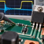
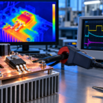
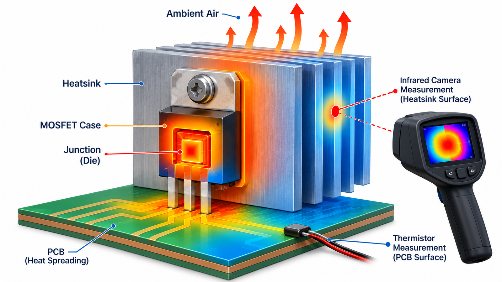
Monitor a MOSFET by measuring case, tab, heatsink, or nearby PCB temperature and translating that result to the junction temperature that governs reliability. Direct junction sensing is rarely available in a discrete device. A thermistor, silicon sensor, thermocouple, infrared camera, or electrical parameter can provide a proxy, but each has placement and bandwidth limitations.
The purpose determines the method. Development characterization may need high spatial resolution, while field protection needs a rugged, repeatable sensor and a safe shutdown threshold.
Choose the measurement point
A sensor on the package top is convenient but may be far from the main heat-flow path in a bottom-cooled package. A sensor near the drain pad can track PCB heating yet be influenced by neighboring components. A heatsink sensor responds slowly and depends on interface quality. Read the package thermal model before selecting a location.
Place production sensors consistently and minimize electrical exposure to switching nodes.
Thermocouple and thermistor methods
A fine thermocouple can capture local surface temperature with modest disturbance if attached using a thin, suitable material. Long metal leads can pick up common-mode switching noise and may compromise isolation. An NTC thermistor is inexpensive and easy to monitor but needs calibration, bias-current control, and a conversion curve.
Ensure adhesive and insulation survive the voltage, temperature, and environment.
Use infrared measurements carefully
A thermal camera is excellent for finding hotspots and comparing devices, but shiny metal tabs and mold compounds have different emissivity. Reflections can produce false readings. Apply a small known-emissivity target where safe, set camera parameters, allow thermal equilibrium, and maintain consistent viewing geometry.
Infrared shows surface temperature, not an instantaneous junction peak hidden inside the package.
Estimate junction temperature
For steady conditions, a first estimate uses junction-to-case or junction-to-ambient resistance times power, but only when the stated thermal path and boundary conditions match the assembly. For pulses, use transient thermal impedance and the actual loss waveform. Complex PCB paths often benefit from calibrated simulation or characterization.
MOSFET thermal calculation explains the loss-to-temperature workflow.
Electrical temperature proxies
RDS(on) usually increases with silicon temperature and can serve as a temperature-sensitive electrical parameter after calibration. The measurement must account for current, gate voltage, package and interconnect resistance, and switching noise. Body-diode forward voltage is another possible proxy under controlled test current, but interrupting normal operation may be necessary.
These methods are useful in laboratories and integrated smart power devices, not a universal plug-in thermometer.
Set alarms and shutdown thresholds
Allow margin for sensor accuracy, placement offset, thermal lag, production variation, ambient changes, and junction transients. A slow board sensor should initiate shutdown well before the absolute junction maximum. Use hysteresis and a controlled restart policy so the system does not chatter at the threshold.
Compare observed heat with why MOSFETs get hot and fix excessive loss rather than relying only on shutdown.
Turn the answer into a robust MOSFET design
For How to Monitor MOSFET Temperature, create an operating-state table before choosing a device or protection value. Include off, startup, steady on, PWM transitions, shutdown, reverse current, load connection, controller reset, brownout, open load, overload, and short circuit. For each state, write the expected VGS, VDS, current, duration, repetition, and starting temperature. This exposes short but severe events that an average-current calculation hides.
Next, compare the table with guaranteed data-sheet limits and characterized curves. Use voltage margin for supply tolerance and ringing; use RDS(on) at the actual gate voltage and hot junction; use total gate charge and Miller charge for driver sizing; and use DC or pulsed SOA for intervals where voltage and current coexist. Include package, PCB copper, interface material, airflow, connector, and source-return inductance in the model. A transistor cannot be evaluated separately from its commutation path and gate loop.
Build a staged test plan that begins with limited available energy. Capture gate-to-source voltage at the pins, drain-source voltage, current, and temperature while changing one stress at a time. Repeat enough cycles to reveal cumulative heating and recovery behavior. Define pass limits before looking at the waveform, preserve oscilloscope files, and record device lot, ambient, probe method, and firmware revision. If measured peaks approach an absolute maximum, redesign for margin rather than accepting the result because one prototype survived.
Practical validation checklist
Validate at the worst credible supply voltage, load current, switching frequency, ambient temperature, and fault condition. Measure gate-to-source voltage at the device pins, drain-to-source voltage with adequate bandwidth, current, case temperature, and—when power or pulses are significant—estimated junction temperature. Account for probe ground inductance and avoid interpreting ringing created by the measurement setup as circuit behavior.
Compare every result with the data-sheet safe operating area, absolute maximum ratings, transient thermal impedance, and temperature-dependent curves. Test startup, shutdown, load connection, stalled or shorted load, controller brownout, and repeated operation. The guides to reading MOSFET safe operating area and MOSFET thermal calculation provide useful companion checks.
Frequently asked questions
Can I measure MOSFET junction temperature directly?
Usually not in a discrete device; estimate it from calibrated surface or electrical measurements and the thermal path.
Is an IR camera accurate on a metal tab?
Not without emissivity and reflection control. A prepared reference spot improves reliability.
Where should I put an NTC?
Near the dominant heat path but electrically safe and mechanically repeatable; validate its offset and lag to the junction.
Can temperature monitoring replace a heatsink?
No. Monitoring detects or limits overheating; it does not remove the heat generated during normal operation.