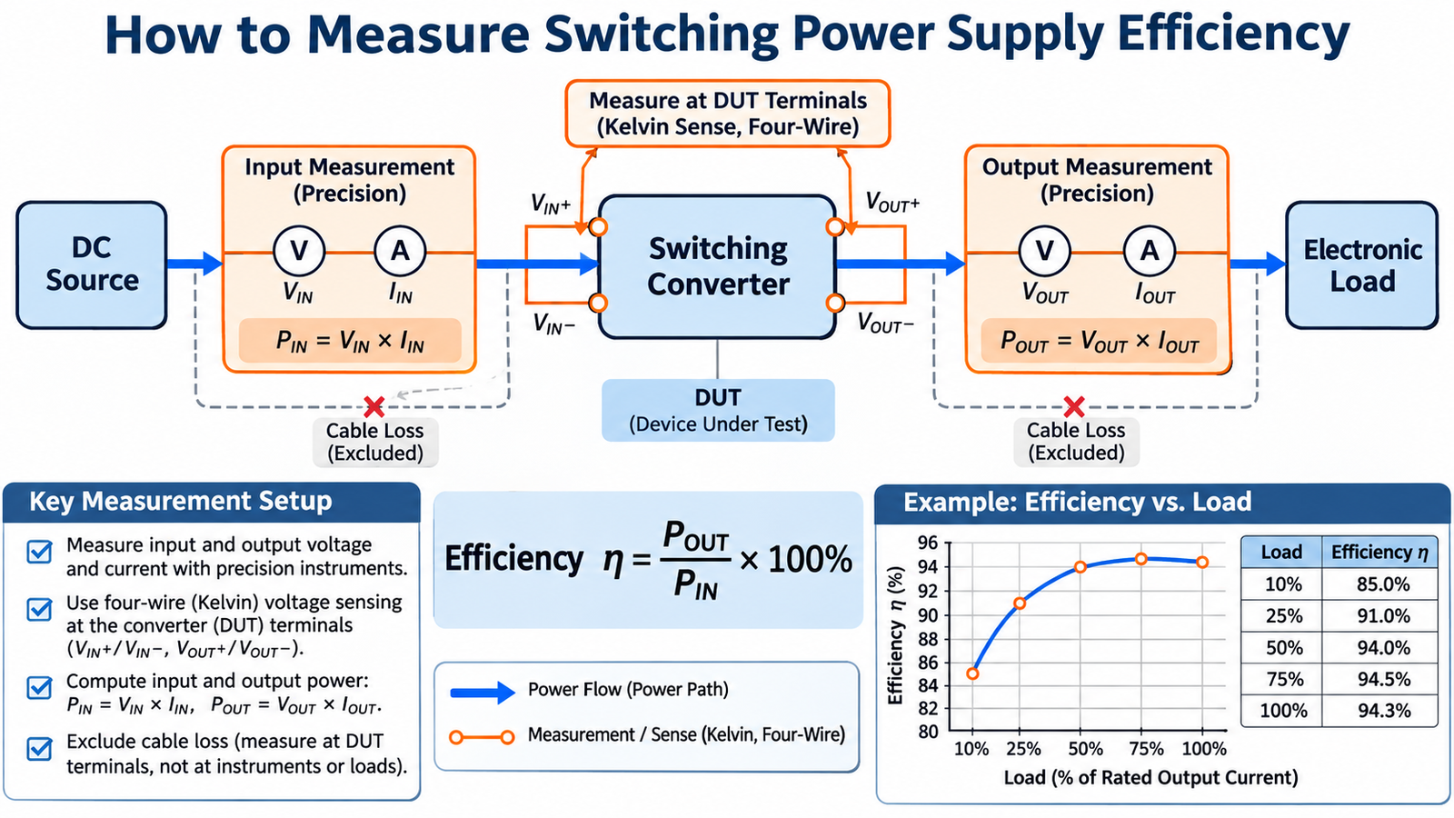
Switching power supply efficiency is η = POUT ÷ PIN × 100%. Measure real input and output power at the device-under-test terminals, after the converter has reached thermal stability, and repeat the measurement across input voltage and load. For AC input, use a power analyzer that measures real watts; multiplying RMS voltage by RMS current is not valid when current is distorted or phase shifted.
Start with the correct power equation
For a DC-output converter, calculate:
POUT = VOUT × IOUT
η = POUT / PIN × 100%
For a DC-input converter, PIN = VIN × IIN,AVG when the instruments measure the average values at the converter input. The input capacitor supplies pulsed switching current locally, so a meter placed at the wrong point can include cable loss or report an unstable average. For an AC-input supply, real input power is the time average of instantaneous voltage times current. Apparent power in volt-amperes is not the denominator of efficiency.
This distinction matters when evaluating a switching power supply, because switching and rectifier currents are not simple DC waveforms inside the converter.
Build a measurement setup that excludes fixture loss
| Measurement | Preferred connection | Main error to avoid |
|---|---|---|
| Input voltage | Kelvin sense directly at the DUT input terminals | Including drop in source leads, fuse, connector or current shunt |
| Input current | Precision shunt, current meter or power analyzer in series | Insufficient bandwidth or incorrect averaging |
| Output voltage | Kelvin sense at the DUT output terminals | Measuring at the electronic load after cable drop |
| Output current | Calibrated electronic load or precision shunt | Trusting a coarse front-panel reading without verification |
Use separate force and sense conductors where practical. If the supply uses remote sense, define whether efficiency includes the remote-sense wiring and keep that definition consistent. Let the converter, magnetics and semiconductors reach a repeatable temperature before recording a steady-state point.
Measure the complete operating envelope
- Set the input to its minimum specified value and verify the output at no load.
- Increase load through useful points such as 10%, 25%, 50%, 75% and 100% of rated current.
- Record input watts, output watts, efficiency, case temperature and operating mode at each point.
- Repeat at nominal and maximum input voltage.
- Repeat after thermal stabilization and, when required, at the temperature limits.
A converter may enter pulse skipping, burst mode or discontinuous conduction at light load. That behavior can produce an efficiency curve very different from the full-load result. If a minimum load is required, apply the guidance in the minimum-load discussion rather than hiding the preload loss.
Account for uncertainty before comparing two designs
Efficiency is a ratio of four measured quantities, so small errors can dominate when loss is small. If a 100 W converter is near 95% efficiency, total loss is only about 5 W. A combined 1 W measurement error changes the inferred loss by roughly 20%, even though the displayed efficiency moves by only about one percentage point.
- Use the instrument accuracy at the actual range, not only the headline specification.
- Zero current probes and shunts before the run.
- Measure voltage and current simultaneously when the operating point changes.
- Keep output leads short and use remote sense only as the product intends.
- State whether fans, gate-drive supplies and auxiliary rails are included.
Worked efficiency example
Suppose the DUT terminals read 12.00 V and 2.00 A at the input, while the output reads 5.00 V and 4.50 A. Input power is 24.0 W, output power is 22.5 W, and efficiency is 93.75%. The inferred converter loss is 1.5 W. If the output voltage were measured at the load after a 0.10 V cable drop, the calculation would incorrectly assign 0.45 W of cable loss to the converter. This is why four-wire voltage sensing matters even when the voltage error appears small.
At very light load, instrument offset and auxiliary consumption become a large fraction of the result. Select lower current ranges where safe, measure standby power separately, and avoid subtracting two large, uncertain numbers to infer a tiny loss.
Use loss and temperature as a cross-check
The difference PLOSS = PIN − POUT should be consistent with semiconductor, magnetic, capacitor and control losses. A large unexplained loss often points to a measurement-location error, a hot connector or an operating mode that was not captured. Device selection also affects the curve; for example, the tradeoff between conduction and switching loss described in MOSFET selection for a buck converter changes with load.
Do not compare an SMPS to a linear regulator at one operating point and generalize the result. The useful comparison depends on input-to-output ratio, standby consumption, thermal limits and noise requirements, as outlined in linear versus switching power supplies.
Efficiency measurement checklist
- Real input power and DC output power are measured at the DUT terminals.
- Input and output instruments are within range and recently verified.
- Cable and fixture losses are either excluded or explicitly included.
- Light-load modes, auxiliary rails and fan power are documented.
- Line, load and temperature sweeps are complete.
- The reported value includes conditions and an uncertainty estimate.
These measurements belong in the validation phase of a complete switch-mode power-supply design. For component support based on the actual voltage, current, switching frequency and thermal target, contact MOT.