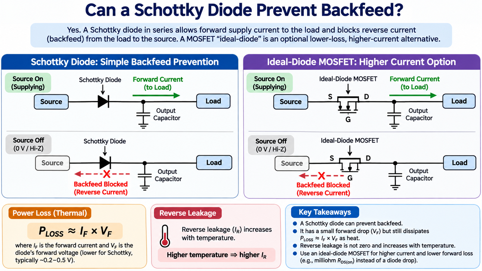
Yes. A Schottky diode placed in series with the source can allow forward supply current and block backfeed when the source is off or lower than the load-side voltage. It is simple and fast, but it is not an ideal open circuit: reverse leakage increases with temperature, and the forward drop creates loss during normal operation.
Orient the diode for the intended power flow
Connect the anode toward the normal source and the cathode toward the load for positive-rail blocking. When the source voltage exceeds the load-side voltage by the diode’s forward voltage, current flows. When the load side rises above the source, the diode is reverse-biased and blocks most reverse current.
Confirm polarity with the circuit examples in how to connect a Schottky diode. Reversing the device can leave the load unpowered or allow an unintended path through another component.
Calculate forward loss and voltage headroom
Approximate conduction loss with PD = IF × VF. VF depends on current and junction temperature; use the data-sheet curve or specified maximum near the real operating point. At 3 A and 0.4 V, the diode would dissipate about 1.2 W, which may require substantial copper area or a larger package.
The load receives approximately VLOAD = VSOURCE − VF. On a low-voltage rail, this lost headroom can be more important than the heat itself.
Reverse leakage means “blocked” is not zero
Schottky reverse leakage can rise by orders of magnitude with junction temperature. For a battery-backed node, supercapacitor or long hold-up interval, even microamps or milliamps may violate the energy budget. Check maximum leakage at the highest reverse voltage and temperature, not only the room-temperature typical value.
Also ensure VRRM exceeds the largest reverse differential, including hot-plug events, inductive transients and another supply driving the load side. The tradeoffs behind low VF, fast switching and leakage are explained in Schottky diode operation and selection.
Check surge and startup current
An output capacitor can draw a large inrush current when connected. Select the diode’s repetitive current, non-repetitive surge rating and thermal impedance for the actual charging pulse. A fuse or current-limited source does not automatically protect the diode during the first milliseconds.
When to use a MOSFET ideal diode
At higher current, a controlled MOSFET can reduce normal loss to approximately IRMS2 × RDS(on). The controller senses forward and reverse differential voltage, turns the MOSFET on for forward current and turns it off rapidly before significant reverse current flows.
A single MOSFET may still conduct through its body diode in one direction when off. Back-to-back MOSFETs are needed when the power path must block both polarities or provide a true load disconnect. See MOSFET reverse-polarity selection for orientation and stress checks.
Backfeed in multi-source systems
When two supplies feed one rail, test every combination: source A on/B off, B on/A off, both on at unequal voltage, startup and shutdown. A blocking diode prevents the higher rail from driving the lower source through the intended power pin, but USB, communication, enable and protection pins can create parallel paths. Add current measurements to each inactive source during the test.
For redundant supplies, diode ORing is simple but the forward drop reduces load voltage. An ideal-diode controller can prioritize sources and reduce loss, but its response time and MOSFET orientation must still prevent reverse current during fast transients.
Estimate hold-up and discharge behavior
When the source turns off, the blocking diode isolates the output capacitor. A first estimate of hold-up time is t ≈ C × ΔV / ILOAD for a roughly constant load current. Reverse leakage, load current and downstream quiescent current all discharge the capacitor. Measure the real decay at maximum temperature, where Schottky leakage is highest.
If fast source reconnection is possible, also check the surge current when the source rises above the held output. The diode may see repeated high-current charging pulses even though the steady load is modest.
Backfeed design checklist
- The diode orientation matches normal power flow.
- VRRM covers every source/load voltage combination and transient.
- IF(AV) and IFSM cover steady current and inrush.
- VF loss and junction temperature are acceptable.
- Maximum hot leakage meets the hold-up or battery budget.
- Alternative current paths through data, ground or protection pins are checked.
Frequently asked questions
Does a Schottky diode stop all reverse current?
No. It blocks the main reverse path but still has leakage, especially at high temperature. The circuit may also backfeed through other pins or ground connections.
Can I put the diode on the ground return?
It can block current, but it shifts the load ground and may create unsafe signal-current paths. Positive-rail blocking is usually easier to integrate and analyze.
Compare MOT small-signal Schottky diodes for low-current paths and the broader power diode range for higher-current designs.