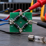
To connect a Schottky diode correctly, identify the anode and cathode, decide which direction current should flow, and orient the device so it is forward biased only during the intended condition. On many axial and molded packages, a band marks the cathode. Surface-mount codes, dual-diode packages, and bare symbols vary, so the manufacturer’s pin drawing is more reliable than package appearance.
A Schottky diode is not connected the same way in every circuit. A series reverse-polarity protector, a buck-converter catch diode, an inductive flyback clamp, a power OR-ing path, and a rail clamp each impose a different normal bias. Start with function and current path, then verify polarity.
Read the symbol and package marking
The diode symbol has an anode on one side and a cathode bar on the other. Conventional forward current enters the anode and leaves the cathode. On a common single diode, the physical band normally corresponds to the symbol’s cathode bar. With power removed, a multimeter in diode mode should usually show a low forward reading with red on the anode and black on the cathode, then open circuit when the probes are reversed.
Do not assume every stripe or laser mark means cathode. Common-cathode, common-anode, and series-connected dual Schottky packages have three pins and internal connections that must be taken from the data sheet. The guide to checking a Schottky diode explains how to verify each junction without confusing parallel circuit paths.
Connect it in series for reverse-polarity protection
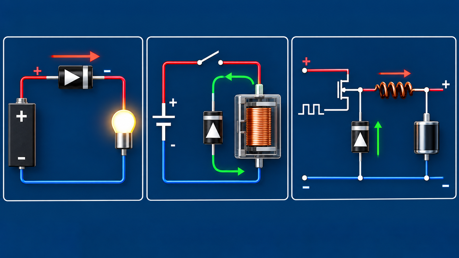
For a simple positive-rail protector, connect the anode to the positive source and the cathode to the protected load. Correct polarity forward biases the diode; a reversed source blocks. The load receives the source voltage minus the diode’s forward drop. This approach is simple, but the loss equals current multiplied by forward voltage and can become significant at high current.
Choose the reverse-voltage rating for the worst negative input and transients, not just the nominal supply. Confirm that hot reverse leakage will not partially power the load. At higher current, an ideal-diode MOSFET arrangement may reduce loss, but it adds gate-control and transient considerations.
Connect a flyback diode across an inductive load
Across a DC relay coil or solenoid, the diode is normally reverse biased: cathode to the positive side of the coil and anode to the switched low side. When the switch opens, coil current continues in the same direction and forward biases the diode, clamping the voltage. Reversing that diode would create a near short whenever the load is powered.
A low Schottky forward drop also means slower current decay and possibly slower relay release than a higher-voltage clamp. Check whether the application needs a diode, diode-plus-Zener network, TVS, or active clamp. Size repetitive current, pulse energy, and junction temperature from the coil current and operating rate.
Use it as a rectifier or catch diode
In a rectifier, orient the diode so it conducts during the desired source polarity and blocks during the opposite interval. In an asynchronous buck converter, the catch diode usually has its anode at ground and cathode at the switching node. It conducts in the interval when the high-side switch is off and inductor current must continue.
Switching applications require more than a polarity check. Reverse voltage, diode capacitance, hot leakage, current waveform, package inductance, and thermal path affect efficiency and stress. Review when a Schottky diode is appropriate before replacing an ultrafast silicon, SiC, or synchronous rectifier.
Place and route the device correctly
Keep a high-di/dt diode loop short and wide. Put a flyback diode close to the coil or connector it protects, and place a converter catch diode close to the switch and input bypass path. Excess trace inductance creates overshoot even when the schematic orientation is correct. Provide copper area or a heatsink according to the package’s characterized thermal path.
Observe creepage and clearance at elevated voltage. If the cathode tab is electrically connected to the package metal, an uninsulated heatsink can become live or short multiple devices together. Check the package drawing before mounting.
Verify before full-power operation
With power absent and capacitors discharged, check continuity paths and diode polarity. First energize from a current-limited source at reduced energy. Measure voltage on both sides, forward drop under realistic current, reverse voltage in the blocking interval, and case temperature after thermal equilibrium. An oscilloscope may be required to see switching overshoot.
The article on Schottky diode operation and selection provides the device background, while rectifier-diode fundamentals help relate polarity to AC-to-DC current paths.
Engineering checklist
Write down the intended current direction in normal, startup, shutdown, reverse-input, and fault conditions. Mark the maximum forward current, surge duration, reverse voltage, switching frequency, ambient temperature, and available cooling. Compare those conditions with data-sheet curves rather than headline ratings. Forward voltage rises with current, while Schottky reverse leakage can rise sharply with voltage and temperature.
Inspect the exact suffix and package pinout during production; visually similar dual diodes can have different internal arrangements. Use a polarized PCB outline, readable reference designator, and unambiguous assembly drawing. Validate high-line, low-line, no-load, full-load, hot, cold, repeated startup, and fault recovery. If the diode repeatedly fails, investigate surge energy, ringing, inadequate copper, load shorts, and nearby switching devices instead of merely installing a larger part.
Frequently asked questions
Does the band on a Schottky diode always mark the cathode?
It commonly does on single packaged diodes, but manufacturer markings and multi-diode pinouts vary. Confirm the data sheet.
Which way should a flyback Schottky diode face?
Across a positive DC coil, cathode normally goes to the positive side and anode to the switched low side, so it is reverse biased while energized.
Can a Schottky diode be connected directly across a supply?
Only as part of a protected clamp arrangement with a fuse or current limit. A forward-biased diode directly across an unrestricted supply can fail violently.
Why is the connected diode getting hot?
Forward-current pulses, high duty cycle, excessive leakage, insufficient copper, wrong package assumptions, or a reversed/misapplied connection can cause heating.