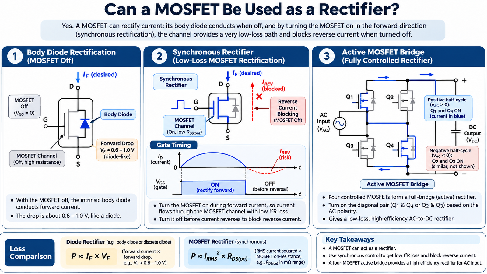
Yes, a MOSFET can be used as a rectifier, but the useful low-loss behavior comes from actively controlling its channel. With the gate off, the intrinsic body diode behaves like an ordinary diode. In synchronous or ideal-diode operation, the controller turns the channel on for forward current and off before current reverses. An active bridge uses four controlled MOSFETs to rectify both AC half-cycles.
Body-diode rectification is not synchronous rectification
Most discrete power MOSFETs contain an intrinsic body diode. When forward-biased, it can carry current with the MOSFET channel off. Its forward drop, reverse recovery and thermal behavior must be treated like a power diode. The physical reason for this path is described in why MOSFETs have a body diode.
The diode may be useful during dead time, startup or commutation, but it is usually not the lowest-loss steady rectifier. Not every MOSFET structure presents the same accessible body diode, so check which MOSFETs have body diodes before assuming one is available.
How synchronous rectification reduces loss
A diode’s conduction loss is approximately P ≈ IAVG × VF. When a MOSFET channel is fully enhanced, conduction loss is approximately P ≈ IRMS2 × RDS(on). At low voltage and high current, the channel can dissipate much less power than a diode drop.
The controller first allows the body diode to establish the correct current direction, then drives the gate on. It must remove gate charge before current reverses. Leaving the channel on too long creates reverse current, shoot-through or energy returned to the wrong rail.
Dead time is a loss-versus-risk tradeoff
Long dead time forces current through the body diode and increases conduction and reverse-recovery loss. Short dead time risks overlap between switches. Optimize timing at minimum and maximum load, input voltage and temperature, following the measurement approach in synchronous-rectifier dead-time optimization.
Check common-source inductance and driver return routing. A few nanohenries can create a gate-voltage error during high di/dt and change the effective turn-off time.
Can one MOSFET behave as an ideal diode?
A single MOSFET can provide a low-loss forward path when its orientation and controller are correct. However, its body diode still conducts in one direction when the channel is off. Use back-to-back MOSFETs when the off state must block current in both directions.
An ideal-diode controller monitors the small voltage across the MOSFET, drives the gate during forward current and turns it off quickly when the voltage indicates reversal. Gate-drive supply, startup and fault behavior must be checked; the term “ideal” does not eliminate RDS(on), leakage or response delay.
How an active MOSFET bridge works
Four MOSFETs can replace the four diodes in a full-wave bridge. The controller determines AC polarity and turns on the diagonal pair that routes current to the positive DC output. On the opposite half-cycle, it turns on the other pair. This reduces two diode drops to two MOSFET channel drops.
The bridge requires safe zero-crossing behavior, gate-drive power for every device, reverse-current control, inrush management and a startup path through body diodes. A useful comparison with conventional rectification is available in MOSFET regulator-rectifier operation.
Select MOSFETs for rectifier duty
| Parameter | Why it matters |
|---|---|
| VDS rating | Must cover AC peak, DC bus and transients |
| RDS(on) at actual VGS | Sets channel conduction loss |
| QG and QGD | Set driver current, transition time and timing error |
| Body-diode QRR | Affects commutation loss and voltage overshoot |
| SOA and avalanche | Define tolerance of inrush and abnormal commutation |
| Thermal resistance | Converts calculated loss into junction temperature |
Compare losses with an illustrative calculation
At 10 A, a 0.5 V diode drop represents about 5 W during conduction. A MOSFET with 8 mΩ RDS(on) would have about 0.8 W of channel conduction loss at 10 A RMS before switching, body-diode and driver losses are added. This example shows why synchronous rectification is attractive, but it is not a complete efficiency prediction.
Gate-drive power is approximately QG × VDRIVE × fSW per device, and commutation loss can dominate at high frequency. Calculate total loss across the complete load range rather than comparing only VF with RDS(on).
Validate before claiming an efficiency gain
- Measure current direction, VDS and VGS for both commutation edges.
- Verify body-diode conduction interval and reverse-recovery current.
- Check reverse current at light load and zero crossing.
- Test startup, shutdown, brownout, inrush and short circuit.
- Compare total MOSFET plus driver loss with the original diode loss.
- Repeat over line, load and temperature.
Frequently asked questions
Can I use a MOSFET as a diode without a controller?
The body diode works without a controller, but channel-based low-loss rectification needs correct gate control. A simple gate-source connection does not create an ideal diode.
Can a MOSFET bridge rectify mains directly?
Only with devices, isolation, gate drives, creepage, protection and control designed for the full hazardous-voltage system. It is not a drop-in four-diode replacement.
Start device selection with MOT’s power MOSFETs, then validate the complete controller, timing, fault and thermal design.