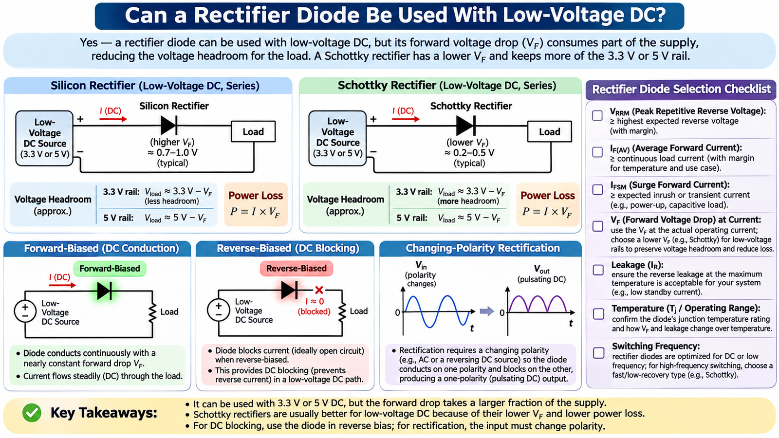
Yes. A rectifier diode can be used with low-voltage DC as a forward-current path, reverse-polarity blocker or flywheel path. Under steady DC it does not perform repeated rectification unless polarity changes; it simply conducts when forward-biased and blocks when reverse-biased. The main low-voltage problem is forward drop, which can consume a large fraction of a 3.3 V or 5 V rail.
Understand what the diode does under DC
A forward-biased diode carries current continuously after the circuit reaches steady state. A reverse-biased diode ideally behaves as an open circuit, apart from leakage. Repeated rectification requires an AC or reversing waveform so the diode alternates between forward and reverse bias.
These operating modes follow the same one-way conduction described in rectifier diode fundamentals. The device name does not prevent its use in a DC blocking or freewheeling function.
Calculate voltage headroom and loss
For a series diode, approximate:
VLOAD = VIN − VF
PD = IF × VF
VF is not one constant number. It changes with current, junction temperature and device construction. Use the specified maximum or curve at the actual current. A 0.7 V drop consumes more than one fifth of a 3.3 V rail before cable and regulator losses are included.
Silicon rectifier or Schottky rectifier?
| Characteristic | Silicon PN rectifier | Schottky rectifier |
|---|---|---|
| Forward drop | Usually higher | Usually lower at comparable current |
| Reverse recovery | Can range from slow to ultrafast | No minority-carrier recovery, but capacitive current remains |
| Reverse leakage | Usually lower | Often higher and strongly temperature-dependent |
| Voltage range | Broad, including high voltage | Commonly favored at lower voltage |
The broader tradeoff is explained in Schottky versus normal diodes. For a low-voltage switching converter, a Schottky device may improve efficiency, but hot leakage and reverse-voltage margin still require calculation.
Choose ratings for the real circuit
- VRRM: exceeds maximum reverse voltage and transients with margin.
- IF(AV): covers continuous average current at the real thermal condition.
- IFSM: covers inrush, capacitor charging and fault pulses.
- VF: meets voltage-headroom and power-loss budgets at the actual current.
- IR: meets standby or hold-up requirements at maximum temperature.
- trr and capacitance: suit the switching frequency and commutation slope.
Common low-voltage DC uses
Reverse-polarity protection
A series diode blocks a reversed source but reduces the normal load voltage. At higher current, a MOSFET reverse-polarity circuit may waste less power.
Inductive flywheel path
A diode across a relay, solenoid or motor carries current after the switch turns off. Its current, energy, recovery and clamp-voltage effect must match the load.
Power ORing and backfeed blocking
Diodes can isolate two sources, but each forward drop matters. Hot leakage can allow unwanted current into an inactive source.
DC/DC freewheeling rectifier
The diode commutates every switching cycle, so reverse recovery, junction capacitance and layout matter. The reason many low-voltage buck stages use Schottky rectifiers is detailed in buck-converter diode selection.
Illustrative low-voltage comparison
With a 5 V source and 1 A load, a silicon diode at 0.8 V would leave roughly 4.2 V for the load and dissipate about 0.8 W. A Schottky diode at 0.35 V would leave roughly 4.65 V and dissipate about 0.35 W. These are illustrative operating points, not universal diode drops; use the exact device curves at current and temperature.
A standard silicon rectifier can still be the better choice when leakage, high temperature or reverse-voltage rating matters more than a few tenths of a volt. The circuit requirement determines the technology.
Alternatives when the diode drop is too large
A MOSFET reverse-polarity or ideal-diode circuit can reduce forward loss on a low-voltage rail. A dedicated load switch may add current limiting, controlled inrush and true shutdown. For a freewheeling path, synchronous rectification can replace the diode during normal operation but requires safe timing. Compare the extra control complexity, standby current and fault behavior with the simple diode before changing architectures.
Validation checklist
- Measure VF and load voltage at minimum and maximum current.
- Calculate dissipation and estimate junction temperature.
- Measure reverse leakage at the hottest expected condition.
- Apply startup and inrush pulses with controlled energy.
- For switching use, observe recovery current and voltage overshoot.
Frequently asked questions
Will a rectifier diode work from a 3.3 V supply?
Electrically yes, but the remaining voltage may be too low for the load. Use the actual VF at current and temperature, then consider a lower-drop Schottky or MOSFET solution.
Does a diode convert steady DC into different DC?
No. It adds a forward drop when conducting or blocks current when reverse-biased. It does not change steady DC voltage by conversion in the way a regulator does.
Compare the required voltage, current, package and temperature with MOT’s power diode portfolio. For application-specific selection, contact MOT.