Identify a Zener diode from its part marking and datasheet when possible. Ordinary silicon rectifiers and Zeners can give similar forward readings in diode mode. A Zener is specified to operate in reverse breakdown at a stated current. A low-energy, current-limited reverse test can support the identification after the part has been isolated from the circuit.
Read the marking and circuit role
The cathode band tells you orientation. Both types can have similar packages and bands, and short surface-mount markings can be reused across manufacturers. Look for the board designator, schematic symbol, placement and BOM. A part wired across a rail or gate with a feed resistor may be a clamp or reference. A part in series with a power path or in a bridge may be a rectifier. Treat those clues as evidence and confirm the part where possible.
A Zener data sheet typically lists VZ at a specified IZ, tolerance and dynamic resistance. A rectifier usually lists repetitive reverse voltage, forward current, surge current and forward drop. Some TVS and avalanche-rated devices also exhibit a reverse knee, so the reverse curve alone may establish a clamp function without identifying the intended part. See the rectifier selection overview for the relevant ratings.
Use a meter to find polarity and obvious faults
De-energize the circuit and verify its capacitors have discharged. Lift one lead or remove the diode if surrounding components alter readings. Test both directions in diode mode. One forward reading and one reverse open reading are consistent with either a silicon rectifier or many Zeners. A reverse open reading can simply mean the meter cannot reach the Zener knee. A reverse reading in circuit can come from another path.
Set up a bounded reverse test
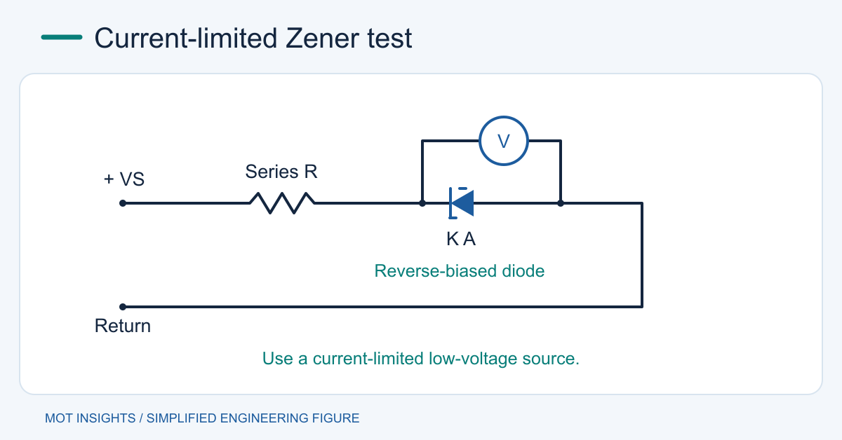
For a suspected low-voltage Zener with a plausible rating, connect the cathode toward positive through a resistor and the anode to the return. Use a low-voltage bench supply with current limiting, and measure the voltage across the device. For a known or documented candidate, select the resistor from R = (VS − VZ)/IZ, with volts and amperes giving ohms. Also check the worst-case resistor and device power if the candidate voltage differs.
For example, a nominal 5.1 V device at a target 2 mA from a 9 V source suggests roughly 1.95 kΩ. A 2 kΩ resistor limits short-circuit current to 4.5 mA. Verify both power ratings and compare the observed voltage only with data at a comparable current. A Zener specified at 5 mA may read lower near its knee at 2 mA. Nexperia’s BZX84 series data illustrates why the test current matters.
Interpret ambiguous results
A stable reverse voltage as current changes modestly is evidence of a clamp knee within the measured range. A near-zero reading can indicate a short or accidental forward connection. If reverse current stays negligible, the device could be a rectifier or a Zener whose knee is above the test voltage. Leave an unidentified part unresolved when identification would require unsafe voltage or stress beyond its documented rating. Do not deliberately avalanche an unknown rectifier to identify it.
For a replacement, confirm the operating role as well as the package. A clamp needs the correct working voltage, tolerance and power behavior. A rectifier needs forward, reverse, surge and recovery ratings for its waveform. Review Zener substitution limits and compare the applicable Zener diode family.