In a common long-channel MOSFET model, beta (β) is the transconductance parameter that sets the scale of drain current for a given gate overdrive. Its unit is amperes per volt squared. Some references fold a factor of one-half into the coefficient, and some simulators use a process parameter before applying device geometry. Read the defining equation before using the number.
Decode the symbol in the equation you have
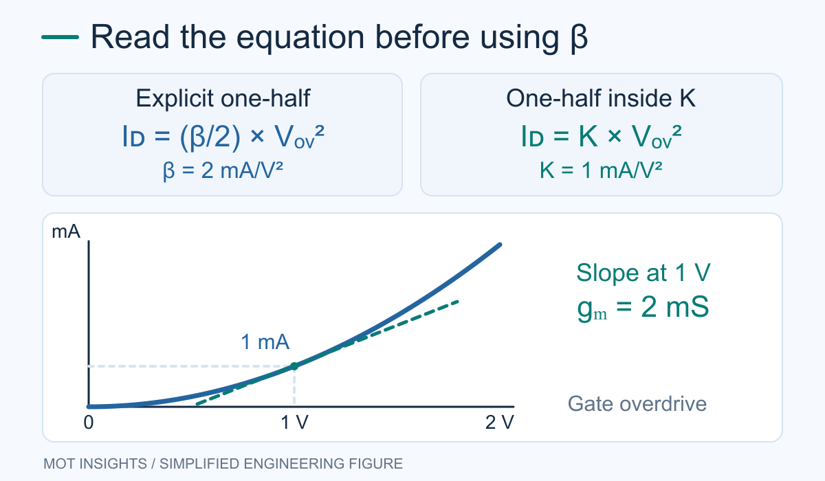
For an ideal enhancement NMOS above threshold with fixed body bias, define overdrive as VOV = VGS − VTH. When VDS is at least VOV, the basic saturation model gives ID = (β/2)VOV² with β = μCox(W/L). Here μ is mobility, Cox is oxide capacitance per unit area and W/L is the effective channel aspect ratio. This expression ignores channel-length modulation and other second-order effects.
| What a source writes | What its coefficient represents | How to use it |
|---|---|---|
| ID = (β/2)VOV² | Geometry-scaled parameter μCoxW/L | Apply the explicit factor of 1/2 |
| ID = K VOV² | Coefficient that already includes 1/2 | K = β/2 for the same device |
| Basic SPICE MOS KP parameter | Often process term μCox for a classical model | Check the model documentation and how geometry is applied |
The labels may vary by text or model. Copy the formula and units alongside any number. Entering a geometry-scaled number as a process parameter and then multiplying by W/L a second time can distort the predicted current by a large factor. Power-device vendor models may use a very different set of parameters. See how to add a MOSFET model in LTspice.
Worked example with a region check
Take an illustrative long-channel NMOS biased at VGS = 2.5 V, VTH = 1.5 V and VDS = 2 V. The overdrive is 1 V and VDS ≥ VOV, so the saturation equation applies under the simplified assumptions. With β = 2 mA/V², ID = (2 mA/V² ÷ 2) × (1 V)² = 1 mA. The other convention uses K = 1 mA/V² and predicts the same 1 mA. Inserting K = 1 into the equation that already divides by two predicts 0.5 mA.
Now hold the gate at the same voltage and reduce VDS to 0.2 V. The operating point is in the triode region of the ideal model. Use ID = β(VOVVDS − VDS²/2). This gives about 0.36 mA. Applying the saturation equation here would overestimate the drain current. A circuit with a source resistor changes VGS as current changes, so solve the resistor relationship and then check the assumed region. The MOSFET DC circuit guide walks through that procedure.
Separate beta from gm and from power-switch ratings
Under the ideal saturation model, gm is the derivative of drain current with respect to gate-to-source voltage at fixed drain voltage and body bias. In the first convention, gm = βVOV. For the 1 V example, this gives 2 mS. Beta has units A/V² and sets the current curve’s scale. Transconductance has units A/V and tells you how much current changes for a small gate-voltage perturbation around the chosen operating point. In a real datasheet or on the bench, extract the local slope at the relevant conditions. Use the MOSFET transconductance guide for that measurement.
For a switch expected to operate fully on, use guaranteed RDS(on) at the available gate voltage and consider temperature, drive and load current. Check gate charge, safe operating area and switching loss under the actual operating conditions. Square-law beta gives useful hand-calculation intuition, but a single fitted value cannot stand in for all those specifications. For a starting point, see the medium- and low-voltage power MOSFET range.
Can I estimate beta from a transfer curve?
In a region where the square-law approximation is reasonable, choose points measured at the same VDS and temperature with fixed body bias. If VTH is known for the model, estimate β ≈ 2ID/VOV² and repeat it at nearby points. A more defensible fit uses a linear region in a plot of √ID versus VGS. In the ideal model the slope is √(β/2). If the inferred value changes sharply with gate voltage, use the manufacturer’s model or treat the fit as local to the operating range. The datasheet threshold specification may be defined at a small current and can differ from the intercept of a model fit.
For a quick consistency check, the worked model predicts 0.5625 mA at 0.75 V of overdrive and 1 mA at 1 V. Both points recover β = 2 mA/V². If a real curve gave 0.56 mA and 0.82 mA at those same overdrives, the estimates would be about 1.99 and 1.64 mA/V². That spread is a reason to check the chosen threshold, temperature and operating region before trusting the fit.
Does MOSFET beta mean the same thing as BJT beta?
In this context MOSFET beta is a model coefficient with electrical units. BJT beta commonly denotes the ratio of collector current to base current in forward-active operation. That ratio is dimensionless. Always identify the device and equation before interpreting the symbol.