For a low-voltage DC heated bed, route heater power through a MOSFET stage rated for the bed’s continuous current, while the printer controller supplies only the control signal. Add a correctly sized fuse, suitable wire and terminals, secure strain relief, and thermal runaway protection. This article does not cover mains-voltage beds, which need certified isolation and installation by qualified personnel.
Before wiring, measure bed resistance with power removed and estimate current as I = V/R. Confirm with the bed and supply specifications because resistance changes with temperature and wiring adds loss.
Select the power stage
Choose a reputable DC MOSFET module or engineered board whose voltage, continuous current, connector, PCB copper, and cooling ratings exceed the real load at enclosure temperature. Marketing current numbers without test conditions are not enough. A discrete design needs proper gate drive, pull-down, clamping, current path, and thermal layout.
The guide to using a MOSFET as a switch explains why logic-level drive and hot RDS(on) matter.
Wire the power path
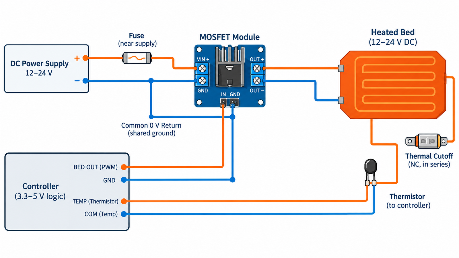
With all power disconnected, route supply positive through a fuse located near the supply, then to the heater or module as specified. A common low-side arrangement places the MOSFET between heater negative and supply negative. Follow the exact module markings because terminal order varies. Use copper sized for continuous current, temperature, bundling, and acceptable voltage drop.
Crimp proper ferrules or lugs; do not tin stranded wire under screw terminals where solder creep can loosen the joint.
Connect the control interface
Verify the module input voltage, polarity, threshold, isolation, and required current. Some boards expect the controller’s heater output, while others accept logic. If the input is non-isolated, a common ground is normally required; if it is optically isolated, grounding rules depend on the circuit. Never guess from a connector color.
Keep control wiring away from the high-current loop and confirm the bed is off during controller boot and reset.
Control connector heating
Many heater failures occur at connectors rather than in the transistor. Contact resistance produces I²R heat and can worsen as terminals loosen or oxidize. Use connectors with a genuine continuous rating, adequate creepage for the voltage, strain relief, and an enclosure that contains a fault. After several heat cycles, inspect torque according to manufacturer guidance and look for discoloration.
Do not route bed current through a controller connector that is not rated for it.
Enable temperature safety
Firmware thermal runaway detection should stop power when temperature rises too slowly, overshoots, or becomes implausible. Secure the thermistor mechanically and electrically so it cannot fall away while reporting a low temperature. Add an independent thermal fuse or cutoff where the risk analysis requires it.
A MOSFET stuck short can leave the heater on despite firmware commands, so the system must not rely on software alone.
Commission under observation
First power from a current-limited or fused source, command a low duty cycle, and verify control polarity. Then test full heat-up while measuring supply voltage, heater current, voltage drop across terminals, MOSFET case temperature, connector temperature, and bed temperature uniformity. Stop if insulation smells, terminals discolor, or temperature rises unexpectedly.
Review MOSFET thermal performance before accepting a module that feels merely warm during a short test.
Turn the answer into a robust MOSFET design
For How to Connect a Heated Bed to a MOSFET Safely, create an operating-state table before choosing a device or protection value. Include off, startup, steady on, PWM transitions, shutdown, reverse current, load connection, controller reset, brownout, open load, overload, and short circuit. For each state, write the expected VGS, VDS, current, duration, repetition, and starting temperature. This exposes short but severe events that an average-current calculation hides.
Next, compare the table with guaranteed data-sheet limits and characterized curves. Use voltage margin for supply tolerance and ringing; use RDS(on) at the actual gate voltage and hot junction; use total gate charge and Miller charge for driver sizing; and use DC or pulsed SOA for intervals where voltage and current coexist. Include package, PCB copper, interface material, airflow, connector, and source-return inductance in the model. A transistor cannot be evaluated separately from its commutation path and gate loop.
Build a staged test plan that begins with limited available energy. Capture gate-to-source voltage at the pins, drain-source voltage, current, and temperature while changing one stress at a time. Repeat enough cycles to reveal cumulative heating and recovery behavior. Define pass limits before looking at the waveform, preserve oscilloscope files, and record device lot, ambient, probe method, and firmware revision. If measured peaks approach an absolute maximum, redesign for margin rather than accepting the result because one prototype survived.
Practical validation checklist
Validate at the worst credible supply voltage, load current, switching frequency, ambient temperature, and fault condition. Measure gate-to-source voltage at the device pins, drain-to-source voltage with adequate bandwidth, current, case temperature, and—when power or pulses are significant—estimated junction temperature. Account for probe ground inductance and avoid interpreting ringing created by the measurement setup as circuit behavior.
Compare every result with the data-sheet safe operating area, absolute maximum ratings, transient thermal impedance, and temperature-dependent curves. Test startup, shutdown, load connection, stalled or shorted load, controller brownout, and repeated operation. The guides to reading MOSFET safe operating area and MOSFET thermal calculation provide useful companion checks.
Frequently asked questions
Can I connect a heated bed directly to a printer controller?
Only if the controller output, connector, PCB, fuse, and cooling are explicitly rated for the bed’s continuous current.
Does the MOSFET module need a common ground?
Many non-isolated modules do; isolated inputs vary. Follow the exact circuit documentation.
Where should the fuse go?
Near the power source in the positive feed, sized to protect the wiring and system while tolerating normal heater current.
Can this circuit switch a mains heated bed?
No. Use a certified mains-rated solution with proper enclosure, grounding, overcurrent protection, and qualified installation.