A MOSFET BLDC electronic speed controller uses three half-bridges, a gate driver and a controller that commutates the motor from rotor-position information. Size the switches from phase current and maximum bus stress. Include hardware overcurrent shutdown, controlled dead time and a way to manage regenerative energy before spinning the motor on a current-limited bench.
Define the motor and DC bus
Record battery or supply minimum and maximum voltage, wiring length, rated and peak phase current, motor winding resistance and inductance, expected speed range, and duty cycle. Document whether the source can absorb returned energy. A bench supply that only sources current can see a rising bus voltage during braking. A battery or its protection circuit may also refuse charging under certain conditions.
Phase current determines device and winding stress. At low speed and low PWM duty, large phase current can circulate even when the average current drawn from the source is modest. Specify the stall and acceleration conditions separately. Provide a current limit consistent with the motor, switches, copper, connectors and source protection.
Build three half-bridges
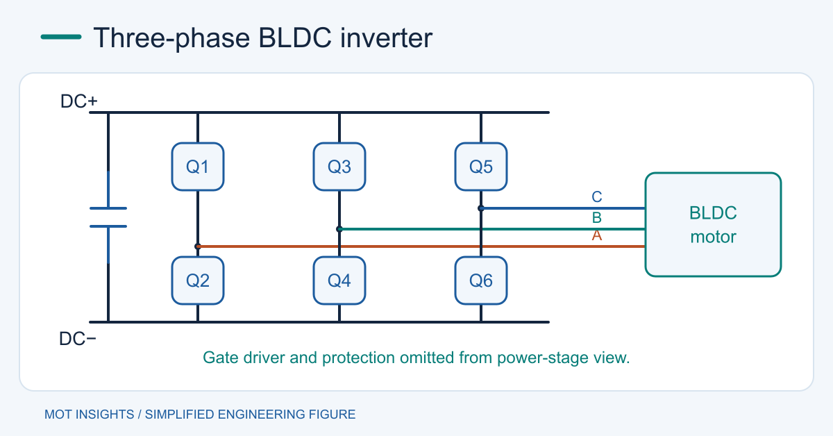
Each phase node sits between a high-side and a low-side switch. Use a three-phase driver with suitable bus rating, source and sink capability, and defined outputs when its logic or bias is missing. For high-side N-channel MOSFETs, use the driver’s documented bootstrap, charge pump or floating supply arrangement. A bootstrap may require periodic refresh and may limit sustained high duty cycle. The MOSFET driver guide explains the supply reference and gate-charge requirements.
Place the high-frequency DC-link capacitor close to the bridge. Keep the commutation loops short, return gate-drive currents to the relevant source terminals and separate current-sense routing from switching-node copper. Verify VDS overshoot and VGS at the pins. Use worst-case hot RDS(on), charge curves at actual bias and the intended PWM frequency when comparing switches.
Start with a valid commutation table
In one illustrative six-step sequence the commanded phase pairs are A+/B−, A+/C−, B+/C−, B+/A−, C+/A− and C+/B−. The third leg is commanded off for each step. Actual recirculating current may still pass through diodes or controlled switches during PWM and commutation. The mapping between Hall states and phase pairs depends on the motor’s wiring and sensor alignment. Verify the sequence at low energy before applying torque.
A sensorless controller often measures back EMF on the undriven phase after a blanking interval. At standstill and very low speed the signal may be insufficient. Use a controlled alignment and startup strategy, then transition to feedback after reliable detection. Hall sensors or another position sensor simplify startup under load when low-speed torque matters.
Coordinate dead time, current sensing and fault handling
Command a short interval with both switches in one leg off around transitions. Choose the interval from actual gate behavior and driver propagation tolerances. Longer intervals can increase diode conduction loss. Short intervals can allow overlap and destructive shoot-through. Verify both edges at line and temperature using synchronous switching dead-time methods.
Include hardware overcurrent detection with a defined shutdown path independent of the normal firmware loop. Verify fault timing and the path for winding energy after gates turn off. A shunt topology must support the required measurement windows. Include bus overvoltage, driver undervoltage, stalled-rotor and thermal policies. Set recovery behavior explicitly so a controller reset cannot restart an unsafe motor.
Bring up the hardware in stages
Estimate the loss and braking headroom
For a first thermal estimate, assume one high-side and one low-side channel carry 20 A in a six-step conduction interval. With 6 mΩ hot resistance per channel, the conducting path dissipates 4.8 W during that interval. PWM freewheeling and phase commutation change the share of time each device conducts. Use the RMS current in each device for its conduction loss, then add switching and diode energy. Equal average power per leg is plausible in balanced operation and can break down during startup, a stalled rotor or an asymmetric fault.
If 1000 µF of DC-link capacitance rises from 24 V to 30 V, it absorbs only 0.162 J, using ½C(Vfinal² − Vinitial²). The example shows why a small DC link alone may have little braking-energy capacity. Estimate the motor and load energy for the actual deceleration, then design a rated absorption path or a braking strategy compatible with the source. Check capacitor voltage, ripple current, and pulse and thermal limits of any clamp or braking resistor.
Verify timing before connecting the motor
Validate firmware outputs and dead time with the power stage disabled. Test one leg at a time with limited energy, then measure phase order and current on an unloaded secured motor with any propeller or driven mechanism removed. Increase current gradually while logging DC-link peaks, switching waveforms, and device temperature. Test an abrupt command change and verify the bus response with the chosen braking strategy. Use the inductive switching protection guide and compare power MOSFETs with the measured stress and available drive.