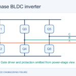
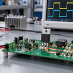
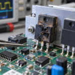
Remove a MOSFET from a de-energized PCB by heating all of its soldered joints until they release together. A leaded package and an exposed-pad power package need different tooling. Inspect the pads, verify the replacement pinout and electrical limits, and check the original failure cause before powering the board. Motherboard VRM work requires particular care around low-resistance rails and integrated power stages.
Identify the failed part and its footprint
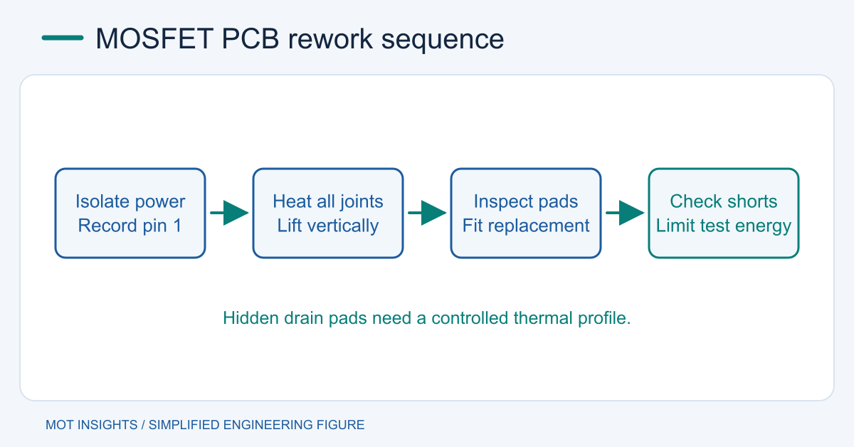
Disconnect every supply and battery and verify stored energy has been discharged using the equipment procedure. Offline supplies can retain hazardous voltage after disconnection. Their primary-side repair belongs with qualified technicians and the correct fixture. Use ESD protection for low-voltage board work and photograph the component orientation, pin-one mark and adjacent passives.
Confirm the board designator and top marking against a known schematic, board documentation or the manufacturer data sheet. A power stage can integrate a driver and two switches in a footprint that resembles a discrete MOSFET. On a motherboard a naturally low core-rail resistance can resemble a short. Compare the suspect phase with a known good phase and apply the motherboard MOSFET fault checks before removing parts.
Match heat delivery to the solder joints
A small leaded device may release with hot tweezers or a suitable soldering iron technique if every joint can be kept molten together. A large drain tab or hidden thermal pad usually needs controlled hot air and sometimes bottom preheat. The board copper plane carries heat away quickly. Choose a nozzle that heats the footprint evenly and set airflow low enough to avoid moving nearby parts.
Use a temperature profile suited to the solder alloy, package and board stack-up. The station’s display temperature describes the tool setting and can differ substantially from the joint temperature. On a multilayer board, measure near the package with a thermocouple where possible. Support the PCB, shield vulnerable connectors where appropriate and limit the time surrounding components remain hot. TI’s QFN assembly guidance illustrates the use of controlled preheat and a localized removal nozzle.
Lift only after all joints release
Apply suitable flux and heat the component evenly. Lift straight up with gentle pickup only after the part moves freely. If a corner stays fixed, stop and correct heat delivery. Pulling against a partially solid pad can lift copper, tear vias or break an internal connection. Allow the board to cool under control.
Use flux and solder wick to level residual solder without scraping the pads. Inspect under magnification for lifted lands, bridged pads, damaged solder mask and displaced neighbors. Verify that the drain pad, gate resistor and source path still connect to the expected nets. For exposed pads, control solder volume so the new part sits flat. Hidden-joint inspection may need X-ray in production or reliability-critical repair.
Select and place the replacement
Match polarity, package orientation and every terminal, including the exposed pad and any separate Kelvin-source terminal. Compare VDS and VGS ratings, hot RDS(on), gate charge, body-diode behavior, safe operating area and thermal path. A substitute with much larger gate charge can overload the original driver or change dead time. See the MOSFET selection guide for the relevant conditions.
Use the board assembly process for flux, solder volume and heating profile. Verify placement and inspect visible joints after cooling. In a synchronous VRM, inspect the opposing switch, gate resistor and driver supply. A shorted load or a driver that leaves both devices on can destroy the replacement on first power-up.
Validate in stages
With power removed, compare resistance and diode-mode readings against neighboring phases or a known-good board. The MOSFET multimeter procedure explains body-diode polarity and the effect of charged gates. If the board supports it, restore power through an approved current-limited setup, then check rail sequencing, gate behavior, load response and temperature. Record part number and waveforms before returning the board to service. For substitute selection, share the original marking and operating conditions with MOT technical support.