In normal steady-state operation, almost no DC current flows through an insulated MOSFET gate, but significant transient current flows while the gate voltage changes. The gate behaves mainly as a nonlinear capacitive load. A driver must move charge into the gate to turn the device on and remove it to turn the device off.
This is why a MOSFET can be called voltage-controlled without implying that its driver is powerless. Fast switching may require ampere-scale current pulses even though the average or static gate current is small.
Why steady gate current is small
A thin oxide insulates the gate electrode from the semiconductor channel. At a fixed voltage within ratings, only leakage flows through the ideal gate path. Data sheets specify gate leakage under defined conditions; real PCB contamination, moisture, damaged oxide, or protection components can add more.
The channel current between drain and source is controlled by electric field, not supplied through the gate.
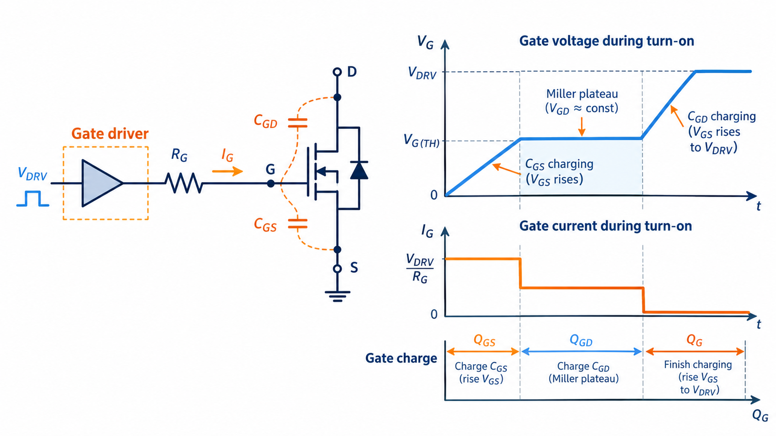
Gate current during turn-on
The driver first charges gate-source capacitance, raising VGS toward threshold. Drain current then rises. During the Miller plateau, much of the driver current changes drain voltage through gate-drain capacitance. Finally, the gate rises to its commanded on voltage. The actual current is shaped by driver resistance, external gate resistor, internal gate resistance, and parasitic inductance.
MOSFET operating fundamentals connect this charge sequence to channel formation.
Gate current during turn-off
To switch off, the driver must sink stored charge. A weak pull-down lengthens the Miller interval and switching loss; a gate left floating can retain charge or be driven by capacitive coupling. Use a gate-to-source resistor to define the off state, but size it so the driver can still reach the required on voltage.
High dV/dt at the drain can inject Miller current and cause false turn-on.
Estimate driver current and power
A useful average gate-drive power estimate is P ≈ QG × VDRIVE × fSW per device, with topology details affecting where that energy dissipates. Peak source and sink current is set by the desired transition time and relevant charge. Do not use only a nominal input-capacitance number because capacitances vary with voltage.
The gate-charge curve is usually more useful for driver sizing.
Understand the role of the gate resistor
The resistor limits peak gate current, damps ringing, and controls dV/dt and di/dt. Too large a value raises switching loss; too small a value can increase overshoot, EMI, driver stress, and bridge cross-conduction. Separate turn-on and turn-off resistances or a diode network can tailor each edge.
Use the gate-resistor tuning procedure rather than copying a universal value.
When DC gate current indicates a problem
A clamp diode can conduct if drive exceeds its threshold; an ESD network may conduct during a transient; an optocoupler or bipolar totem pole may provide another path. Unexpected sustained current can also indicate contamination, incorrect measurement, excessive VGS, or oxide damage. Remove power and discharge the gate before resistance checks.
Never exceed absolute maximum gate voltage to test whether the device turns on more strongly.
Turn the answer into a robust MOSFET design
For Does Current Flow Through the Gate of a MOSFET?, create an operating-state table before choosing a device or protection value. Include off, startup, steady on, PWM transitions, shutdown, reverse current, load connection, controller reset, brownout, open load, overload, and short circuit. For each state, write the expected VGS, VDS, current, duration, repetition, and starting temperature. This exposes short but severe events that an average-current calculation hides.
Next, compare the table with guaranteed data-sheet limits and characterized curves. Use voltage margin for supply tolerance and ringing; use RDS(on) at the actual gate voltage and hot junction; use total gate charge and Miller charge for driver sizing; and use DC or pulsed SOA for intervals where voltage and current coexist. Include package, PCB copper, interface material, airflow, connector, and source-return inductance in the model. A transistor cannot be evaluated separately from its commutation path and gate loop.
Build a staged test plan that begins with limited available energy. Capture gate-to-source voltage at the pins, drain-source voltage, current, and temperature while changing one stress at a time. Repeat enough cycles to reveal cumulative heating and recovery behavior. Define pass limits before looking at the waveform, preserve oscilloscope files, and record device lot, ambient, probe method, and firmware revision. If measured peaks approach an absolute maximum, redesign for margin rather than accepting the result because one prototype survived.
Practical validation checklist
Validate at the worst credible supply voltage, load current, switching frequency, ambient temperature, and fault condition. Measure gate-to-source voltage at the device pins, drain-to-source voltage with adequate bandwidth, current, case temperature, and—when power or pulses are significant—estimated junction temperature. Account for probe ground inductance and avoid interpreting ringing created by the measurement setup as circuit behavior.
Compare every result with the data-sheet safe operating area, absolute maximum ratings, transient thermal impedance, and temperature-dependent curves. Test startup, shutdown, load connection, stalled or shorted load, controller brownout, and repeated operation. The guides to reading MOSFET safe operating area and MOSFET thermal calculation provide useful companion checks.
Frequently asked questions
Why does my gate driver need high current?
It must move gate charge quickly during switching; the current is transient rather than continuous DC gate conduction.
Can a microcontroller drive a MOSFET gate directly?
Sometimes at low frequency and modest charge, but verify voltage, peak current, transition loss, reset state, and protection; a driver is often better.
Does a gate resistor stop all gate current?
No. It limits and shapes charging current; the gate still needs charge for each transition.
What happens if the gate floats?
Capacitive coupling, leakage, or retained charge can partially turn the MOSFET on, causing heat or unpredictable switching.