Short-circuit protection in a switching power supply should combine a fast peak-current limit with a controlled fault response such as hiccup or latch-off. Set the threshold from worst-case peak current—not rated output current alone—then verify every fault path, device stress, startup condition, and recovery mode across line, load, and temperature. Boost-derived topologies may also need a series disconnect because turning off the main switch does not necessarily interrupt the input-to-output path.
Safety note: An offline AC-DC supply contains hazardous voltage and stored energy. Short-circuit testing should use an isolated, current-limited source, correctly rated probes and fixtures, and a documented lab procedure. Do not apply a hard short to an energized mains prototype unless the setup and operator are qualified for the applicable safety requirements.
Define the fault before choosing the circuit
A useful protection specification separates a temporary overload from a hard output short. It should state where the fault can occur, how quickly it must be detected, how much current and energy are acceptable, whether the supply may retry, and how it must recover. This work belongs in the specification stage of a switch-mode power-supply design, not after the power stage has already been laid out.
| Fault case | Main risk | Required response |
|---|---|---|
| Brief overload | Nuisance shutdown or loss of regulation | Controlled current limiting for a defined time |
| Hard output short | Switch, rectifier, inductor or transformer overheating | Fast pulse limiting plus hiccup or shutdown |
| Partial short or resistive fault | High continuous dissipation below the hard-short threshold | Timed overload detection or thermal supervision |
| Short during startup | Repeated charging attempts and magnetic saturation | Current-limited soft start with a retry limit |
| Internal switch or sense failure | Primary protection may be unavailable | Independent fuse, eFuse or secondary protection layer |
Also define the allowed behavior after the fault disappears. Automatic restart is convenient for unattended equipment, while latch-off is often safer when a repeated restart could damage wiring, a load, or another power domain.
Trace the short-circuit current path for the topology
Protection starts with the actual fault loop. Turning off a PWM signal protects only the current paths controlled by that switch.
| Topology | Current path during an output short | Design implication |
|---|---|---|
| Buck | Input, high-side switch, inductor and shorted output | Cycle-by-cycle switch or inductor-current limiting is usually effective, followed by a lower-duty fault mode |
| Boost | Input can feed the output through the inductor and rectifier even when the switch is off | Add an input or output disconnect, protected load switch, fuse or eFuse when a true output disconnect is required |
| Flyback | Primary peak current is reflected to the secondary during energy transfer | Primary current limiting must be coordinated with transformer saturation, secondary rectifier stress and restart timing |
| Synchronous converter | Either MOSFET may conduct depending on timing, body-diode state and reverse-current capability | Confirm protection for both switches and prevent unwanted negative current |
| Multiple outputs | A shorted secondary may not collapse the sensed output | Use per-output protection when cross-regulation cannot guarantee fault detection |
The boost-converter exception is especially important. The basic boost power path can continue carrying current from input to output during a short, so switch current limiting alone is not complete output-short protection. A separate series switch, protected load switch, eFuse, or correctly coordinated fuse is one practical solution when the application requires a true output disconnect.
Set the trip level from peak current, not the nameplate current
The protection threshold must sit above the highest legitimate current—including ripple, load transient, startup and tolerance—but below the lowest damaging current for the switch, magnetics, rectifier, shunt and PCB path.
For a continuous-conduction buck converter, a useful first estimate is:
IL,PK = IOUT,MAX + ΔIL/2
where IL,PK is peak inductor current and ΔIL is the peak-to-peak ripple current. If a controller trips when its current-sense input reaches VCS,TRIP, the nominal shunt estimate is:
RCS = VCS,TRIP / IPK,LIMIT
Do not stop at the nominal result. Calculate both corners:
ITRIP,MIN = VTH,MIN / RCS,MAXITRIP,MAX = VTH,MAX / RCS,MIN
For example, a nominal 100 mV comparator threshold and a 16.7 mΩ shunt suggest 6 A. With a ±10% threshold and a ±1% resistor, however, the actual trip range is approximately 5.34 A to 6.65 A before temperature coefficient, trace resistance, noise and propagation delay are included. This range must be checked against required load current and the worst-case safe current of every stressed component.
A controller may specify peak, valley, or average-current limiting. These are not interchangeable. Some controllers use valley limiting for sustained overloads, a separate peak comparator for the high-side MOSFET, and hiccup operation after an output short. Always use the exact controller’s data-sheet timing diagrams, threshold tolerances, blanking time, and limit equations.
Choose a sensing method that matches the fault speed
| Sensing method | Strength | Main limitation |
|---|---|---|
| Low-value shunt | Accurate, predictable and easy to calculate | Power loss, common-mode range and parasitic inductance |
| MOSFET RDS(on) | No extra series loss | Large tolerance and strong temperature dependence |
| Inductor DCR | Low loss and useful for average current | Needs RC matching and temperature compensation |
| Current transformer | Low loss and isolation at high switching frequency | Cannot measure DC and must be reset correctly |
| Hall or isolated sensor | Measures DC with galvanic isolation | Higher cost, delay and offset than a fast shunt comparator |
Use Kelvin connections from a shunt to the comparator or controller. Keep the high-current copper out of the sense return, and place any RC filter close to the sense input. Leading-edge blanking can prevent false trips from capacitance and diode-recovery spikes, but excessive blanking creates an unprotected interval. The peak current reached during that interval must remain below the switch and magnetic limits.
Use a fast protection layer and a slower fault policy
Fast layer: limit each switching pulse
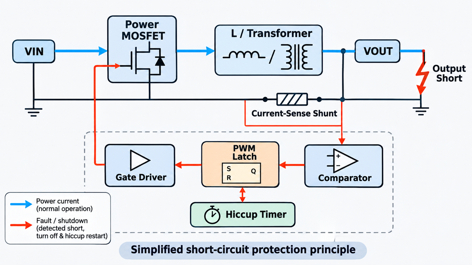
A hardware comparator should terminate or skip a switching pulse before the MOSFET, rectifier or magnetic component exceeds its pulse-current limit. Firmware is normally too slow and too dependent on a functioning clock, ADC and processor to be the only protection against a hard short.
Slow layer: reduce fault energy
Cycle-by-cycle limiting can still leave high average dissipation if the converter continues switching indefinitely. Add a timer, feedback-voltage qualifier, temperature input or restart counter that moves a persistent fault into foldback, hiccup or latch-off. This broader system view complements a component-level design for protecting a MOSFET from overcurrent.
Select the right fault response
| Response | Behavior | Best fit | Watch for |
|---|---|---|---|
| Constant-current limit | Maintains current near a threshold | Loads that must ride through a temporary overload | High continuous dissipation at low output voltage |
| Foldback | Reduces allowed current as output voltage collapses | Reducing heat in switches and rectifiers | Failure to start into a large capacitive or constant-power load |
| Hiccup | Switches briefly, waits, then retries with soft start | Unattended equipment where automatic recovery is desirable | Repeated stress, audible noise and interaction with the load |
| Latch-off | Stops until enable or input power is reset | Safety-critical or redundant systems | Loss of automatic recovery after a harmless transient |
Hiccup protection reduces average fault power by inserting a long off-time between short restart attempts. Latch-off instead holds the converter disabled until enable or input power is reset. Controller manufacturers document both approaches: select the mode from the safe retry energy, the load’s recovery behavior, and the consequence of an unattended restart. For an isolated flyback supply, verify the selected mode at both minimum and maximum line because primary peak current, reflected voltage, demagnetization time, and available fault power all change with operating point.
Check every component that absorbs fault energy
The current-limit threshold protects the system only when the associated energy and voltage stress are safe. At each trip, stored inductor energy is:
EL = 1/2 × L × IPK2
That energy must go somewhere when the switch turns off. Check the MOSFET’s VDS, unclamped inductive energy or avalanche rating, pulsed safe operating area and junction temperature. Then check inductor or transformer saturation, rectifier surge and thermal limits, synchronous MOSFET reverse current, clamp dissipation, shunt pulse rating, connector current and copper temperature. Use the actual switching waveform rather than a DC current number when choosing a MOSFET for a buck converter.
Foldback controllers reduce the permitted peak current as feedback voltage collapses because maintaining the full current limit during a hard short can increase dissipation in the regulator, inductor, and catch diode. Check that the reduced current still permits startup into the allowed output capacitance and load. Thermal shutdown is a backup, not the primary design target.
Coordinate protection with startup and large capacitive loads
A discharged output capacitor initially resembles a short. Estimate its ideal charging current from I = C × dV/dt, then set soft-start time so the required current stays below the protection threshold with margin. A foldback circuit that is too aggressive may never charge the output; a hiccup controller may repeatedly restart without reaching regulation.
Test at maximum output capacitance, minimum and maximum input voltage, cold and hot component values, and the fastest allowed load connection. If the supply must start into a constant-power load, verify that its negative incremental input resistance does not trap the converter in current limit.
Validate with a controlled fault matrix
Use a MOSFET-based electronic shorting fixture or a correctly rated contactor so the fault timing is repeatable. Start with a current-limited source and low available energy, then expand the test envelope only after waveforms confirm safe behavior.
- Apply the short before startup, during startup and at steady-state full load.
- Repeat at minimum, nominal and maximum input voltage.
- Test a hard short, a resistive partial short and a slowly increasing overload.
- Measure switch or inductor peak current, VDS, VGS, output voltage, rectifier current and fault timing with properly referenced probes.
- Verify that the transformer or inductor does not saturate and that clamp voltage remains within margin.
- Run the fault long enough to reach the intended thermal steady state for constant-current, foldback or hiccup operation.
- Remove the short at different points in the retry cycle and confirm monotonic recovery without output overshoot.
- Repeat at the temperature limits and with component tolerances that produce the highest trip current and longest delay.
Record both the first pulse and the long-term retry pattern. A converter can survive one short event but still overheat after hundreds of retries.
Short-circuit protection design checklist
- Fault location and current path are defined for each topology and output.
- Maximum legitimate peak current is calculated across line, load, startup and tolerance.
- Minimum and maximum trip thresholds are calculated, not assumed from a typical value.
- A hardware path limits individual switching pulses.
- A persistent-fault policy limits average energy and temperature.
- Boost and other non-isolating paths include a disconnect where required.
- MOSFET SOA, magnetics, rectifiers, shunt, clamp, PCB and connectors are checked.
- Sense layout uses Kelvin connections and a justified filter or blanking time.
- Startup, capacitive loads and constant-power loads do not create false trips.
- Short application, removal and recovery are verified over voltage and temperature.
Frequently asked questions
Is current limiting the same as short-circuit protection?
No. Current limiting controls instantaneous or average current, but complete short-circuit protection also limits fault duration and energy, handles topology-specific current paths, protects every stressed component, and defines safe recovery.
How far above rated output current should the limit be set?
There is no universal percentage. The threshold must exceed the worst-case legitimate peak current and startup demand, yet remain below the minimum unsafe current after comparator, shunt, temperature, ripple, noise and delay tolerances are included.
Should a switching power supply use hiccup or latch-off?
Use hiccup when automatic recovery is important and repeated restart energy is safe. Use latch-off when an automatic retry could worsen damage, disturb a redundant power system or create a safety risk. Some products use both: limited retries followed by latch-off.
Can a fuse provide all the required protection?
Usually not. A fuse is valuable as independent catastrophic-fault protection, but a semiconductor switch can exceed its pulse or thermal limit before the fuse opens. Coordinate the fuse with fast electronic current limiting and the available source energy.
Build protection around the complete power path
Reliable short-circuit protection is a coordinated system, not one comparator threshold. Start with the topology and fault path, calculate the real peak-current envelope, add fast pulse limiting and a suitable long-fault response, then validate component stress and recovery under controlled faults. MOT offers power MOSFETs and power diodes for switching and protection designs. For help matching voltage, current, switching and thermal requirements, contact the MOT team.