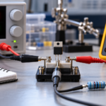
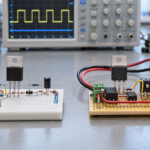
What does a MOSFET do? It uses voltage at its gate to control how much current can flow between drain and source. This allows a small control signal from a microcontroller, analog circuit, or gate driver to route, interrupt, or regulate a much larger current. Depending on its operating point, the MOSFET acts as an efficient electronic switch, an amplifier, a controlled resistance, or part of a protection circuit.
The MOSFET does not create power. It controls power supplied by the rest of the circuit. Its usefulness comes from high input resistance, fast switching, scalable current capability, and the ability to integrate in enormous numbers on a chip.
The two fundamental MOSFET functions
1. Electronic switching
In switching service, the design moves the MOSFET quickly between off and on. Off, it blocks voltage. On, it provides a low-resistance current path. Spending little time between those states reduces power loss.
This function appears in power converters, motor phases, battery disconnects, load switches, LED drivers, and logic circuits. Pulse-width modulation changes the average energy delivered to a load by controlling the percentage of time the MOSFET is on.
2. Amplification and controlled conduction
In analog service, the MOSFET operates between fully off and fully on. Small changes in gate voltage create controlled changes in drain current. The surrounding resistors, current sources, feedback, and load turn that transconductance into voltage gain, current gain, or regulation.
Analog MOSFETs are used in amplifiers, active loads, current mirrors, linear regulators, electronic loads, and signal switches. Linear operation produces simultaneous voltage and current, so safe operating area and heat dissipation need close attention.
What a MOSFET does in common applications
| Application | MOSFET role | Main design concerns |
|---|---|---|
| DC-DC converter | Connects and disconnects the inductor at high frequency | Conduction loss, switching energy, dead time, and layout |
| AC-DC power supply | Controls transformer or boost-inductor energy | Voltage margin, avalanche, capacitance, EMI, and isolation context |
| Motor drive | Forms bridge legs that steer phase current | Current, reverse recovery, shoot-through, gate drive, and thermal cycling |
| Load switch | Turns a supply rail on or off | Inrush current, reverse current, voltage drop, and controlled slew rate |
| Battery protection | Disconnects charge or discharge current during a fault | Back-to-back arrangement, fault current, heat, and gate bias |
| Reverse-polarity protection | Acts as a low-loss ideal-diode element | Body-diode orientation, startup path, and reverse blocking |
| Audio or sensor amplifier | Converts gate-voltage changes into drain-current changes | Bias, gain, linearity, noise, matching, and stability |
| Digital logic | Pulls internal nodes high or low | Leakage, capacitance, delay, noise margin, and density |
How a MOSFET controls a load
Imagine an N-channel MOSFET placed between a load and ground. When the controller holds VGS near zero, the device blocks current and the load is off. When the controller raises VGS high enough, the channel becomes conductive and current flows from the supply through the load and MOSFET to ground.
The controller does not need to deliver the load current into the gate. It must only charge the gate to the required voltage and then discharge it when turning off. A dedicated gate driver may deliver ampere-level current for a brief interval even though average gate current is modest.
What a MOSFET does in a buck converter
A buck converter reduces a DC input voltage. Its high-side MOSFET periodically connects the input supply to an inductor. The low-side MOSFET or diode provides a current path when the high-side device turns off. The inductor and capacitor average the switching waveform into a lower DC output.
The MOSFETs do not set the output voltage independently. A controller measures the output and adjusts duty cycle. The gate driver translates the controller signal into the voltage and current needed at each gate. The magnetics and capacitors store and filter energy.
What a MOSFET does in a motor driver
A half bridge uses two MOSFETs to connect a motor phase alternately to the positive bus and ground. Three half bridges create a common three-phase inverter. By sequencing and pulse-width modulating the switches, the controller sets phase voltage, current, torque, direction, and speed.
Motor inductance keeps current flowing when a switch turns off. The current transfers through another MOSFET channel or body diode. Gate timing must prevent both devices in one bridge leg from turning on simultaneously, which would short the supply.
What a MOSFET does in protection circuits
Reverse-polarity protection
Placed with the correct body-diode orientation, a MOSFET can initially conduct enough to establish gate bias and then turn on its channel. The resulting voltage drop can be much lower than a series diode’s drop. A controller may be required at higher voltage or when fast fault response matters.
Overcurrent and short-circuit protection
An electronic fuse senses current and turns a MOSFET off during a fault. The MOSFET is the interrupting element, but the sensing and control circuit decides when and how quickly to act. During a controlled current limit, the MOSFET may operate linearly and must remain inside its safe operating area.
Bidirectional disconnect
One MOSFET channel can conduct in either direction when on, but its body diode provides an uncontrolled path in one direction when off. Two MOSFETs connected back-to-back oppose their body diodes and can block current in both directions.
What a MOSFET cannot do alone
- It cannot determine a regulated output by itself. A feedback controller sets the required duty cycle or gate bias.
- It cannot guarantee safe switching. A driver, timing logic, protection, and layout control gate behavior and transients.
- It cannot remove its own heat. The package, PCB, heatsink, airflow, and ambient environment establish junction temperature.
- It cannot automatically block both current directions. Body-diode orientation and back-to-back arrangements must be considered.
- It cannot survive every voltage spike because it has an avalanche rating. Repetitive stress, energy, temperature, and reliability limits still apply.
Choosing the MOSFET for the job
For a static load switch
Prioritize voltage margin, hot RDS(on), package thermal performance, inrush behavior, and reverse-current requirements. Gate charge matters mainly during turn-on and turn-off unless switching occurs frequently.
For a high-frequency converter
Balance RDS(on) against gate charge, Miller charge, output-capacitance energy, and body-diode behavior. The lowest-resistance device can have a larger die and higher capacitance, which may increase switching loss.
For linear control
Check the DC and pulsed safe operating area at the intended voltage, current, time, and case temperature. Switching-oriented current ratings do not prove that a device can dissipate high voltage and current simultaneously for long periods.
How to tell whether the MOSFET is doing its job
- Measure VGS directly between gate and source, preferably at the device pins.
- Measure VDS when on. Unexpected voltage may indicate insufficient gate drive, excessive current, or high temperature.
- Observe switching waveforms for overshoot, ringing, Miller behavior, and false turn-on.
- Measure current and calculate RMS and switching conditions rather than relying only on average current.
- Estimate junction temperature from loss and thermal impedance, then confirm case or board temperature in the prototype.
- Test input, load, temperature, startup, shutdown, and fault extremes.
Frequently asked questions
Does a MOSFET reduce voltage?
An on MOSFET produces a voltage drop equal approximately to current multiplied by RDS(on). In a switching converter, controlled switching plus inductors and capacitors creates a different average output voltage. The MOSFET alone is not a complete voltage regulator.
Is a MOSFET a relay?
Both can switch a load, but a MOSFET has no moving contacts and can switch much faster. A relay can provide galvanic isolation and block AC naturally. A MOSFET needs appropriate drive, isolation if required, and attention to body-diode paths.
Does a MOSFET need a resistor at the gate?
A series gate resistor is often used to control peak current, ringing, edge rate, EMI, and driver stress. A gate-to-source pull resistor establishes a defined off state. Exact values depend on the driver, layout, switching frequency, and desired transition speed.
Summary
A MOSFET lets a voltage signal control a current path. Used as a switch, it routes power efficiently. Used in an analog region, it controls or amplifies current. The surrounding controller, gate driver, passive components, protection, PCB layout, and thermal system determine how well that basic function performs in a real product.