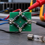
Build a single-phase bridge rectifier by arranging four diodes so the load current always flows in the same direction. Connect the cathodes of two diodes together for the positive output, connect the anodes of the other two for the negative output, and form each AC terminal by joining one remaining anode to one remaining cathode.
Two diodes conduct on every half-cycle, so the output is full-wave pulsating DC. A reservoir capacitor can reduce ripple, but it also creates narrow charging pulses and high startup surge. Begin with an isolated low-voltage AC source, not exposed mains.
Confirm diode polarity
The band on most axial rectifier diodes marks the cathode, but verify the data sheet because package markings vary. Use a multimeter’s diode-test mode to identify forward direction: with the red lead on anode and black lead on cathode, a silicon rectifier normally shows a forward voltage; reversed leads should show open circuit at the meter’s low test voltage.
The overview of rectifier diode construction and ratings explains why a power rectifier differs from a small signal diode.
Wire the four-diode bridge
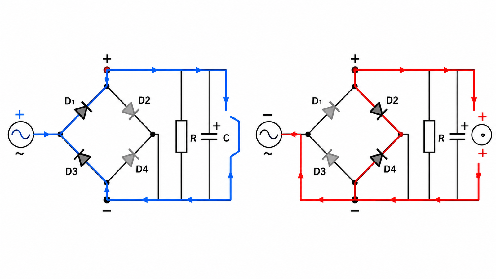
Label the diodes D1 through D4. Join the cathodes of D1 and D2; this is DC positive. Join the anodes of D3 and D4; this is DC negative. Join D1 anode to D3 cathode for one AC input. Join D2 anode to D4 cathode for the other AC input. Inspect every junction before applying power.
If your drawing uses a diamond symbol, trace current rather than relying on visual orientation. The path from either AC terminal to positive must pass through a forward diode, and the return from negative to the opposite AC terminal must pass through another.
Choose voltage ratings with margin
Each diode must block reverse voltage when its diagonal pair conducts. Select repetitive peak reverse voltage for the transformer secondary peak plus line tolerance, transformer regulation, ringing, and transients. Do not confuse RMS voltage with peak: a sine wave’s ideal peak is approximately 1.414 times RMS before tolerances.
The article on why a bridge uses four diodes follows both conduction paths and helps verify the orientation.
Choose current and thermal ratings
The load’s DC current is not the complete diode stress. With a capacitor-input filter, diodes conduct short, high-amplitude pulses near the AC peaks. Check average forward current, repetitive peak current, nonrepetitive surge, forward voltage, thermal resistance, lead temperature, and derating. The transformer and wiring resistance affect pulse amplitude.
Two forward drops are in series during conduction. Estimate bridge heat from actual pulsed current and forward-voltage curves, then provide copper area, spacing, or a packaged bridge with heatsinking when required.
Add a reservoir capacitor carefully
Connect the electrolytic capacitor positive to bridge positive and negative to bridge negative. Its voltage rating must exceed the highest no-load DC peak with margin. A fuse, inrush limiter, bleeder, and discharge indicator may be needed. The capacitor stores hazardous energy after input power is removed.
The approximate ripple depends on load current, capacitance, and full-wave ripple frequency, but real performance also includes transformer impedance, capacitor ESR, diode pulse current, and line variation. Do not size the capacitor from ripple voltage alone.
Test the bridge in stages
With power removed, use diode mode from each AC terminal to positive and from negative to each AC terminal, accounting for probe polarity. Confirm no short exists across AC or DC. First energize from an isolated low-voltage transformer with current limiting or a fuse. Measure AC input, unloaded pulsating DC, and loaded DC. Add the capacitor only after polarity is confirmed.
An oscilloscope ground clip can short a nonisolated circuit through protective earth. Use an isolated source and an appropriate differential measurement method.
Practical design review
For a real product, decide whether four discrete diodes or an integrated bridge gives better assembly, thermal spreading, creepage, surge rating, and traceability. Keep high-current loops short and use conductors sized for pulsed RMS current. Place the reservoir capacitor near the bridge while maintaining safety spacing. If the load is inductive or returns energy, analyze behavior beyond the basic capacitor-input example.
Validate at high line, no load, full load, hot ambient, cold start, rapid restart, and surge conditions. Measure transformer temperature, bridge temperature, DC ripple, and diode current when needed. Compare alternative topologies using the two common full-wave rectifier arrangements. For mains equipment, use certified components, protective enclosure, fusing, earthing, and qualified safety review.
Mark the finished board with AC, plus, and minus labels that remain visible after assembly. A polarity error can instantly damage the capacitor and load. Add test points that cannot be confused, and specify the expected unloaded and loaded voltages in the production test procedure.
Frequently asked questions
How many diodes are needed for a bridge rectifier?
Four diodes are required for a standard single-phase full-wave bridge, and two conduct during each half-cycle.
Can I use four different diode types?
It is poor practice. Use matched parts with adequate voltage, current, surge, speed, and thermal ratings so stress shares predictably between half-cycles.
Why is bridge output lower than the AC peak?
Current passes through two forward-biased diodes, and the transformer, wiring, and capacitor charging pulses add voltage drop.
Does a bridge rectifier produce smooth DC?
No. The bridge produces full-wave pulsating DC. A capacitor and often additional regulation or filtering are needed for a smoother output.