
When one diode in a bridge rectifier fails short, the bridge no longer steers each AC half-cycle safely into the same DC polarity. On at least one half-cycle, the short can combine with another conducting diode to place a very low impedance across the source or transformer winding. A fuse may open immediately; if it does not, wiring, transformer windings, the remaining diodes, or PCB traces can overheat.
The exact symptom depends on which junction shorts, the load, source impedance, fuse, and whether other components failed first.
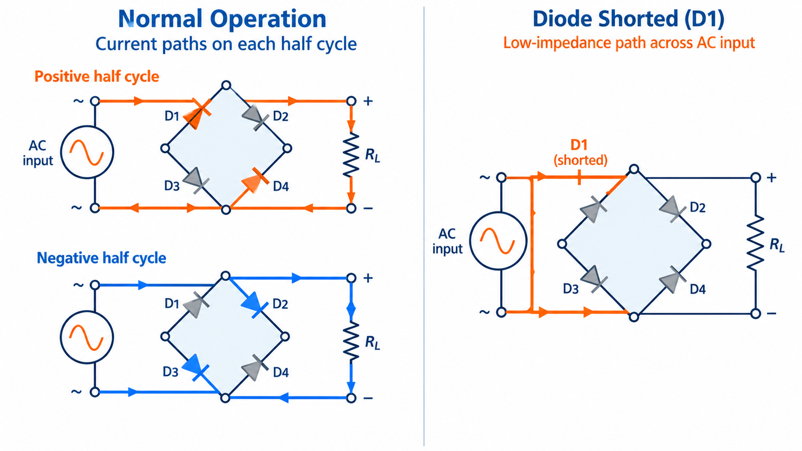
Normal bridge current paths
A full-wave bridge uses four diodes. One diagonal pair conducts during one AC polarity and the opposite pair conducts during the other. The load therefore sees the same DC polarity on both half-cycles. Two diode forward drops are normally present in each conduction path.
The article on bridge-rectifier diode count maps these alternating paths.
How one short changes the circuit
A shorted junction permanently connects two bridge nodes that should be isolated for part of the cycle. During one polarity, another healthy diode can then complete a near-short across the AC input. During the other polarity, output polarity or charging paths may also be wrong. High current is limited mainly by source, winding, wiring, and diode impedance.
It is unsafe to keep replacing fuses to observe what happens; each attempt can compound damage.
Common symptoms
The input fuse may blow at power-on, a current limiter may trip, a transformer may buzz or heat, or a series safety lamp may glow brightly. Output can be zero, low, half-wave-like, or heavily rippled. Burned bridge packages, cracked epoxy, discolored board, or damaged tracks may appear, but a diode can be electrically short without visible damage.
A downstream shorted bulk capacitor can produce similar fuse symptoms and may have caused the bridge failure.
Test the bridge safely
Disconnect power, verify isolation from mains, and discharge high-voltage capacitors using an approved method. Use diode mode to test each of the four internal junctions in both directions, following the AC and +/− pin labels. In-circuit transformers, capacitors, MOVs, and loads create parallel paths, so lift a lead or remove the bridge when readings are ambiguous.
Follow the bridge connection map to identify each junction.
Inspect collateral damage
Check the fuse type and rating, input connector, switch, NTC, EMI components, transformer, PCB traces, bulk capacitor, downstream switch, and load. Test the remaining bridge junctions even if one obvious short is found because surge current may have weakened them. Replace a monolithic bridge as a complete unit rather than trying to repair one internal diode.
Never uprate the fuse simply to prevent nuisance opening.
Prevent recurrence
Verify repetitive reverse voltage, average and surge current, inrush, cooling, capacitor size, line surge environment, and mounting. A large capacitor charges in narrow high-current peaks, so average load current alone understates diode RMS and surge stress. Add correct surge suppression and inrush control where the design requires them.
After repair, energize through an appropriate current-limited setup and monitor input current, DC bus, ripple, and bridge temperature.
Turn the answer into a component decision
For What Happens When a Diode Shorts in a Bridge Rectifier?, begin with a table of the real electrical conditions: normal forward current, RMS and peak current, surge waveform, repetitive reverse voltage, switching frequency, ambient and board temperature, cooling, duty cycle, and allowed voltage drop. Add the abnormal cases—capacitor inrush, output short, reversed connection, open load, and line surge. A family name or familiar part number cannot replace this requirement set.
Compare candidates using guaranteed limits at relevant temperatures. Record the exact test current behind forward voltage, the pulse shape behind a surge rating, and the conditions behind reverse-recovery or capacitance values. Check package polarity, land pattern, terminal current density, copper area, creepage, and whether the part’s metal surface is electrically live. If several junctions share a package or heatsink, include thermal coupling and fault propagation rather than treating each junction independently.
On a prototype, start at reduced available energy and verify polarity before increasing load. Capture current and voltage simultaneously when switching behavior matters. Run long enough to reach thermal equilibrium, then repeat at the hottest input and load corner. Finally, document why the chosen part is suitable and which measurements confirm it. This traceable process is more reliable than substitution by appearance, a room-temperature diode-mode reading, or a single maximum rating.
Practical validation checklist
Confirm the exact part number and polarity before applying power. Check repetitive reverse voltage, average and RMS forward current, surge current, forward drop at the real current, leakage at the hottest credible junction temperature, package thermal resistance, and any recovery or capacitance requirement. A diode that passes a room-temperature multimeter check can still be unsuitable at operating voltage, frequency, or temperature.
Commission with current limiting where practical, then measure loaded forward drop, reverse stress, case temperature, and switching waveform. Inspect fuses, capacitors, connectors, PCB discoloration, and the load when a rectifier has failed; replacing only the visibly damaged diode can leave the initiating fault untouched. See rectifier-diode fundamentals for the wider selection context.
Frequently asked questions
Will one shorted diode always blow the fuse?
Often, but source impedance, fuse size, and the exact failure path can instead produce heating, distorted output, or secondary damage.
Can I test a bridge rectifier in circuit?
You can screen it, but parallel components may mislead; isolate or remove it for a conclusive junction test.
Can a bad filter capacitor short the bridge?
Yes. A shorted or failing capacitor can create severe charging current and may be the root cause.
Should I replace all four discrete diodes?
When one in a matched bridge has suffered a severe fault, replacing the complete set and investigating the cause is often prudent.


