MOSFET thermal performance is calculated in two linked stages: find the electrical power dissipated in the device, then convert that loss into junction-temperature rise through the real thermal path. The arithmetic looks simple, but the inputs are operating-point dependent. RDS(on) rises with temperature, switching energy depends on current, voltage, driver, and layout, and package thermal resistance assumes specific mounting conditions.
A useful result is not merely “the MOSFET dissipates 3 W.” It is a worst-case junction-temperature estimate for defined input voltage, load waveform, switching frequency, ambient or coolant temperature, PCB, interface, airflow, and transient duty.
Build the complete loss budget
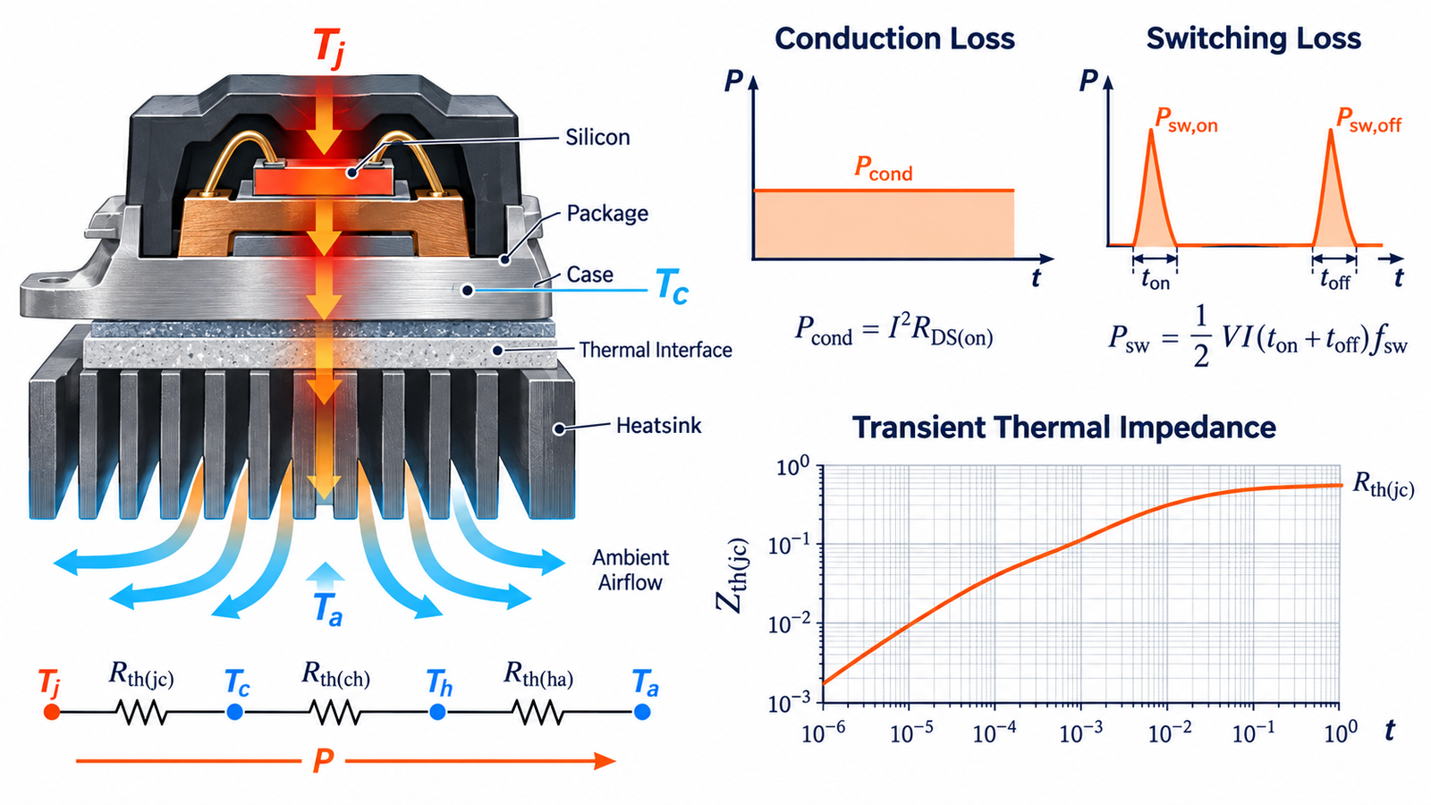
For a hard-switched MOSFET, total loss may include conduction loss, turn-on and turn-off overlap, output-capacitance loss, reverse-recovery interaction, body-diode conduction, gate-drive loss assigned to the driver, and avalanche or linear-mode events. In a simple resistive on-state interval, Pcond is approximately IRMS2RDS(on). Use the resistance at the estimated hot junction temperature and actual gate voltage.
Switching loss can be estimated from measured or data-sheet energy per event multiplied by switching frequency, with careful scaling for voltage, current, gate resistance, and temperature. The discussion of whether switching reduces MOSFET heat explains why lower conduction loss can be offset by dynamic loss.
Choose the correct thermal network
For a package mounted to a controlled case or heatsink, the steady path is often modeled as RθJC + RθCS + RθSA: junction to case, case through the interface to sink, and sink to ambient. Junction temperature is then approximately ambient temperature plus power multiplied by the total path. Add heat from neighboring components or shared sinks when it affects the local ambient.
For surface-mount devices cooled through the PCB, the data-sheet RθJA applies only to the specified test board and copper. A small production layout can be much worse. Prefer vendor thermal models or characterization that resembles the real copper area, layers, vias, airflow, and enclosure.
Iterate because resistance changes with temperature
Start with an estimated junction temperature, read or calculate hot RDS(on), compute loss, then calculate a new junction temperature. Repeat until the result converges. Include tolerances and use maximum resistance where required. If the result approaches the absolute maximum junction rating, the design lacks practical margin for unit variation, blocked airflow, dust, aging, or measurement uncertainty.
The related guide to MOSFET heatsink sizing focuses on selecting RθSA; the broader calculation here also includes dynamic losses and transient behavior.
Use transient thermal impedance for pulses
A short pulse does not instantly heat the entire package and heatsink to equilibrium. Use ZthJC(t, D) or the relevant junction-to-ambient transient curve at the pulse duration and duty cycle. For a rectangular pulse with a controlled case starting temperature, a first estimate is ΔTJ = PpulseZth. Repetitive, irregular, or multi-level waveforms may require superposition or the vendor’s Foster/Cauer thermal network.
Do not substitute steady-state RθJC for every pulse, and do not apply a junction-to-case curve when the case temperature is not effectively controlled. Check electrical safe operating area as well; thermal arithmetic alone does not guarantee linear-mode or avalanche survival.
Measure temperature without fooling yourself
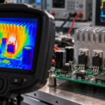
An infrared camera sees package-surface temperature and depends on emissivity, focus, viewing angle, and reflected heat. A thermocouple can alter airflow or electrical isolation and is not the junction. Some devices provide a temperature-sensitive electrical parameter or calibrated diode. Use the manufacturer’s recommended method and relate the measured case or board point to junction temperature with the correct characterization parameter.
Probe switching waveforms with suitable bandwidth and low-inductance connections, then integrate instantaneous voltage times current if a reliable switching-loss measurement is needed. A hotter-than-expected result may come from ringing, slow gate transitions, cross-conduction, insufficient drive voltage, or poor layout rather than the heatsink alone.
Design margin and cooling improvements
Reduce loss through a more suitable MOSFET, lower parasitic inductance, optimized gate resistance, soft switching, synchronous timing, or current sharing. Improve heat flow with more copper, thermal vias, correct pad coverage, interface material, pressure, airflow, or a larger sink. Each change should address the dominant resistance or loss term.
See how heatsinks cool MOSFETs and how PCB thermal paths affect power MOSFETs for physical implementation details.
Engineering checklist
Create a spreadsheet or simulation with named inputs for maximum ambient, coolant, copper loss, semiconductor tolerances, gate drive, frequency, airflow, interface resistance, and neighboring heat. Separate typical and worst-case calculations. Check normal operation, overload, startup, stalled load, pulse bursts, and protection delay. Compare the predicted temperature with the data-sheet maximum and with a lower reliability target.
On prototypes, measure electrical loss and at least one meaningful thermal node across input, load, ambient, and airflow corners. Allow true thermal equilibrium for steady tests, and capture peak junction estimates for fast pulses. Repeat after enclosure assembly, because bench airflow can hide problems. Document mounting torque, pad, paste, copper stack, and sensor location so the calculation remains reproducible in production.
Frequently asked questions
What is the basic MOSFET junction-temperature formula?
For steady state, Tj is approximately the reference temperature plus power times the relevant total thermal resistance. The reference may be case, sink, board, or ambient depending on the data.
Should I use RθJA or RθJC?
Use the parameter that matches the physical heat path and boundary condition. RθJA is board-specific; RθJC assumes heat flows to a controlled case.
How is pulsed heating calculated?
Use the data-sheet transient thermal impedance at the actual pulse width and duty cycle, or convolve the power waveform with a validated thermal network.
Why does the measured case temperature look safe while the MOSFET fails?
The silicon junction can be much hotter than the package surface during fast or localized heating, and electrical SOA limits may be exceeded before the case responds.