You can sometimes redesign a circuit to use a BJT instead of a MOSFET, but a BJT is almost never a drop-in replacement. Both are transistors and can amplify or switch current, yet their input requirements and on-state behavior differ. A MOSFET gate mainly consumes current while charging and discharging capacitance; a BJT needs continuous base current while conducting.
The correct decision depends on voltage, current, switching frequency, available drive, allowed loss, analog behavior, safe operating area, package, and fault requirements.
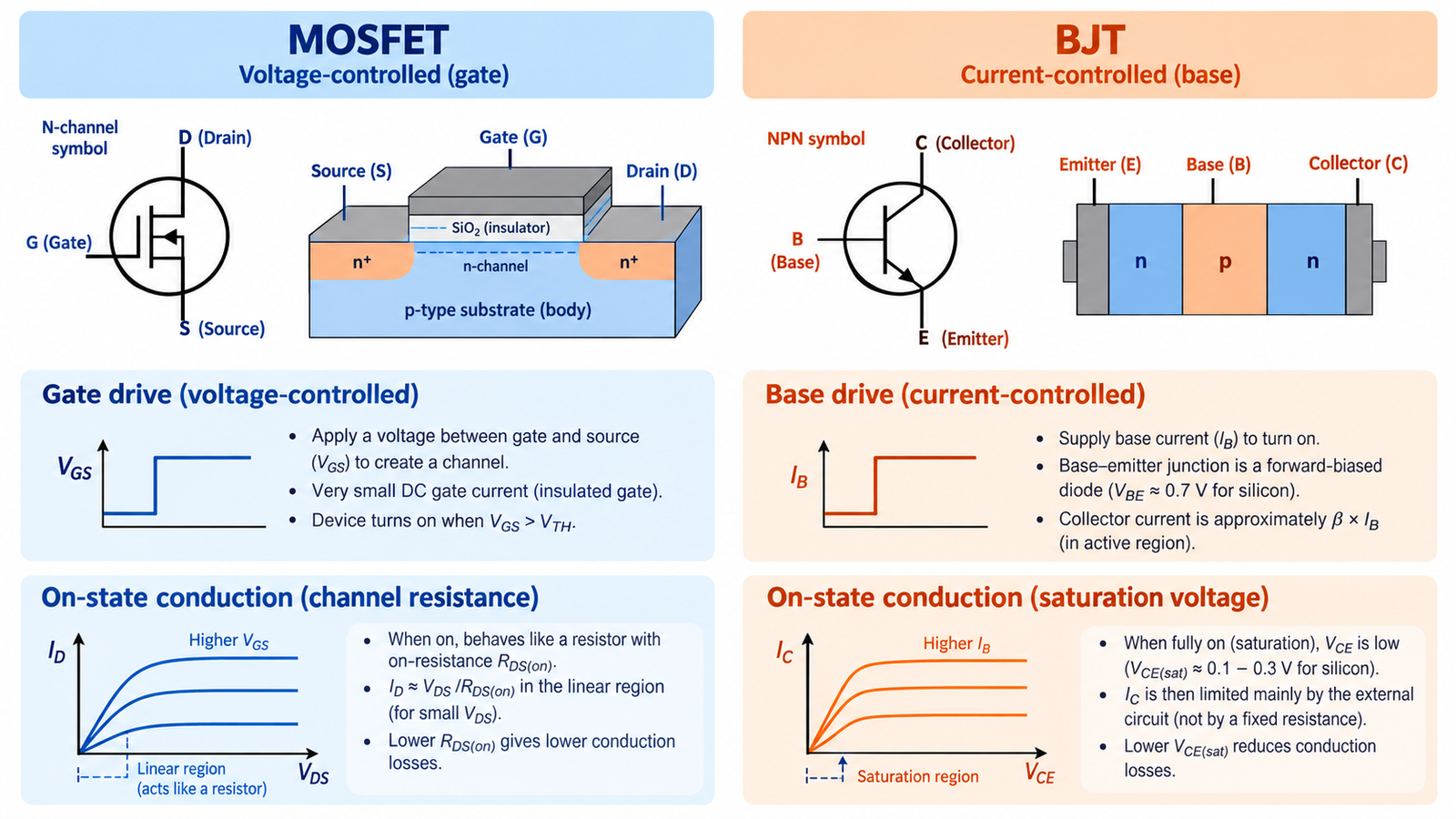
Redesign the drive
A BJT base-emitter junction behaves like a forward-biased diode. To force the transistor into a low collector-emitter voltage, the driver may need base current equal to a meaningful fraction of load current. Add a base resistor, ensure the controller can source and sink the required current, and prevent excessive reverse base-emitter voltage.
A MOSFET gate driver designed only for charge pulses may overheat or fail to provide the sustained BJT base current.
Compare conduction loss
A MOSFET’s on loss is approximately I²RDS(on). A saturated BJT is commonly estimated from I×VCE(sat), but VCE(sat) depends on collector current, base drive, temperature, and device. At low voltage and high current, a modern MOSFET often wins; at high voltage or in specialized analog conditions, the answer can differ.
Use guaranteed hot values, not one typical graph point.
Compare switching behavior
MOSFET switching is dominated by gate charge, Miller charge, capacitances, driver impedance, and circuit inductance. A deeply saturated BJT stores charge that can slow turn-off unless the driver removes it effectively or avoids deep saturation. Switching loss and required dead time may change substantially.
The comparison in when to use a BJT versus a MOSFET provides a broader application view.
Check voltage, SOA, and thermal stability
Match breakdown voltage with transient margin and study the correct safe-operating-area graph. BJTs can suffer secondary breakdown and need attention to current sharing; MOSFETs have their own linear-mode and avalanche limitations. Temperature coefficients affect parallel operation and bias stability differently.
A replacement that survives steady load may still fail during startup, current limiting, or inductive turn-off.
Account for polarity and reverse paths
Confirm N-channel versus NPN or P-channel versus PNP function, but do not assume the symbol correspondence solves the circuit. A power MOSFET normally has a body diode; a BJT does not provide an equivalent low-impedance reverse path. Bridge, motor, and synchronous circuits may depend on that path or on controlled reverse channel conduction.
The article is a MOSFET a transistor? clarifies the family relationship without implying interchangeability.
Treat pinout and mechanics as design inputs
Package names do not guarantee the same pin order, tab connection, isolation, or thermal resistance. Check the exact manufacturer drawing. Recalculate the base network, driver dissipation, snubber or flyback path, heatsink, PCB copper, and fault protection. Update firmware timing if switching delays change.
Prototype with current limiting and capture base or gate waveform, device voltage, load current, and temperature before approving production substitution.
Turn the answer into a robust MOSFET design
For Can You Replace a MOSFET With a BJT?, create an operating-state table before choosing a device or protection value. Include off, startup, steady on, PWM transitions, shutdown, reverse current, load connection, controller reset, brownout, open load, overload, and short circuit. For each state, write the expected VGS, VDS, current, duration, repetition, and starting temperature. This exposes short but severe events that an average-current calculation hides.
Next, compare the table with guaranteed data-sheet limits and characterized curves. Use voltage margin for supply tolerance and ringing; use RDS(on) at the actual gate voltage and hot junction; use total gate charge and Miller charge for driver sizing; and use DC or pulsed SOA for intervals where voltage and current coexist. Include package, PCB copper, interface material, airflow, connector, and source-return inductance in the model. A transistor cannot be evaluated separately from its commutation path and gate loop.
Build a staged test plan that begins with limited available energy. Capture gate-to-source voltage at the pins, drain-source voltage, current, and temperature while changing one stress at a time. Repeat enough cycles to reveal cumulative heating and recovery behavior. Define pass limits before looking at the waveform, preserve oscilloscope files, and record device lot, ambient, probe method, and firmware revision. If measured peaks approach an absolute maximum, redesign for margin rather than accepting the result because one prototype survived.
Practical validation checklist
Validate at the worst credible supply voltage, load current, switching frequency, ambient temperature, and fault condition. Measure gate-to-source voltage at the device pins, drain-to-source voltage with adequate bandwidth, current, case temperature, and—when power or pulses are significant—estimated junction temperature. Account for probe ground inductance and avoid interpreting ringing created by the measurement setup as circuit behavior.
Compare every result with the data-sheet safe operating area, absolute maximum ratings, transient thermal impedance, and temperature-dependent curves. Test startup, shutdown, load connection, stalled or shorted load, controller brownout, and repeated operation. The guides to reading MOSFET safe operating area and MOSFET thermal calculation provide useful companion checks.
Frequently asked questions
Can an NPN replace an N-channel MOSFET?
Only with a redesigned base-drive and protection network and after checking loss, speed, voltage, SOA, and pinout.
Which device has lower voltage drop?
It depends on current and temperature: compare hot I×RDS(on) for the MOSFET with guaranteed VCE(sat) at the available base current.
Can I reuse the MOSFET gate resistor as a BJT base resistor?
Not automatically. Base current is continuous and must be calculated from the BJT and load requirements.
Is an IGBT a better substitute?
Sometimes at higher voltage and power, but it also needs a full switching, loss, tail-current, SOA, and drive analysis.