Measure switching power supply ripple directly across the output capacitor with the smallest possible probe loop, a controlled electronic load, and a stated oscilloscope bandwidth. Use AC coupling when appropriate to remove the DC level, but preserve enough low-frequency response to see burst-mode envelope. A long ground clip can create ringing that is entirely produced by the probe loop.
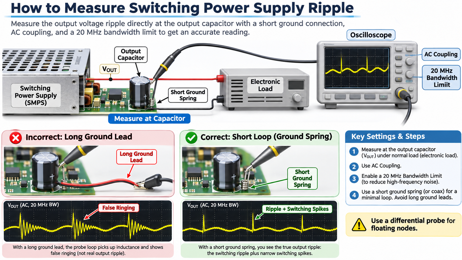
Safety boundary: A bench oscilloscope ground is normally bonded to protective earth. Do not attach it to a floating primary-side or high-voltage node. Use a correctly rated differential probe and an appropriate isolated test method.
Define what “ripple” includes
Output ripple normally contains a switching-frequency component, capacitor-ESR steps and narrow commutation spikes. Burst or skip operation adds a lower-frequency envelope. Load transients add droop and recovery that should be reported separately. State whether the requirement is peak-to-peak ripple, RMS noise, integrated spectral noise or transient deviation.
The waveform depends on topology and operating mode. Review the relevant stage in switch-mode power-supply design before deciding which frequency components are expected.
Connect the probe at the output capacitor
Place the probe tip on the positive capacitor terminal and the ground spring on the adjacent negative terminal. The loop area should be a few millimeters rather than the large loop formed by a standard alligator ground lead. An alternative is a short coax pigtail or dedicated test socket with a controlled termination.
Measuring at the load can be useful for system power integrity, but cable inductance and connector resistance then become part of the result. Label that measurement separately from converter-terminal ripple.
Set the oscilloscope deliberately
| Setting | Starting point | Reason |
|---|---|---|
| Coupling | AC for millivolt ripple on a DC rail | Removes the large DC component and improves vertical resolution |
| Bandwidth | 20 MHz when the specification uses that convention | Limits unrelated high-frequency noise and makes results comparable |
| Probe ratio | 1× or 2× when voltage and bandwidth allow | Avoids attenuating the small ripple into the noise floor |
| Acquisition | Normal sample first; then average or high-resolution as a secondary view | Preserves real spikes before filtering random noise |
| Trigger | Switch node or ripple waveform | Separates periodic switching content from random events |
Do not report only a filtered, averaged waveform. Capture the unfiltered view needed to identify overshoot, then apply the bandwidth required by the product specification.
Test line, load and operating modes
- Measure at minimum, nominal and maximum input voltage.
- Sweep from no load through full rated load.
- Record continuous-conduction, discontinuous, pulse-skipping and burst modes.
- Repeat after the converter reaches thermal equilibrium.
- Apply load steps separately to measure transient response.
A supply with a minimum-load requirement may show large low-frequency excursions when tested below that boundary. Check minimum-load behavior before treating the waveform as a component failure.
Recognize measurement artifacts
- Long ground lead: adds inductance and picks up switch-node magnetic fields.
- Probe touching the switch node: capacitively couples high dV/dt into the ripple channel.
- Ground loop: creates common-mode current through instrument earth connections.
- Over-attenuation: pushes a millivolt signal toward the oscilloscope noise floor.
- Insufficient sample rate: aliases narrow spikes into misleading shapes.
Layout-induced ringing can still be real. Compare a short-loop measurement with the switching nodes and inspect the current loops described in critical-loop PCB layout. Gate transition speed may also affect the spikes; gate-resistor tuning explains the efficiency-versus-EMI tradeoff.
Document a reproducible ripple result
Save the waveform with input voltage, output current, temperature, probe type, connection method, coupling, bandwidth, sample rate and measurement location. Record both peak-to-peak value and the switching or burst frequency. A number without these conditions cannot be compared reliably with a data sheet or another laboratory.
Compare measurement with a first-order estimate
For a buck converter with approximately triangular capacitor current, the capacitive ripple estimate is ΔVC ≈ ΔIL / (8fSWCOUT). The ESR contribution is approximately ΔVESR ≈ ΔIL × ESR. These expressions do not include ESL spikes, control-loop modulation, capacitor derating or layout.
If the observed low-frequency ripple is much larger than the estimate, check burst mode, loop stability and load interaction. If only narrow spikes are excessive, inspect the commutation loop, capacitor ESL and probing method before increasing capacitance.
Repeat the measurement at more than one point on the output plane when the load has fast local transients. A clean waveform at the converter capacitor does not guarantee a clean rail at the load after connector and plane inductance. Treat converter ripple and point-of-load power integrity as related but separate results.
Ripple measurement checklist
- The probe is directly across the output capacitor.
- The ground path is a spring or short coax connection.
- Bandwidth and coupling match the written test method.
- Floating nodes use a differential probe.
- Line, load, operating mode and temperature are recorded.
- Periodic ripple, spikes and load-transient deviation are reported separately.
If ripple remains excessive after the measurement method is verified, review the power stage, control loop, capacitor impedance and layout. For component support, contact MOT with the measured waveform and operating conditions.