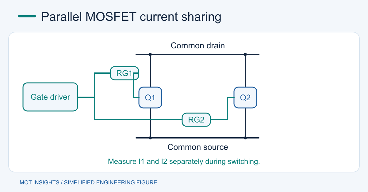
Parallel power MOSFETs by connecting their drains and sources to common nodes through balanced paths and driving each gate through its own resistor. Choose matching devices, then verify individual current during conduction and switching. Equal schematic connections can still produce unequal loss when copper resistance, inductance, gate charge, threshold and temperature differ between branches.
Calculate the static split
For two fully enhanced branches, include the hot channel resistance plus the resistance of their individual copper, joints and any shunts. With equal voltage across the branches, current divides inversely to resistance. If branch A is 4 mΩ and branch B is 5 mΩ at the evaluated temperature, a 45 A total splits to about 25 A and 20 A respectively. Their losses in the total branch resistances are about 2.5 W and 2.0 W. Separate device and copper loss when estimating junction temperature.
Many silicon power MOSFETs have a positive resistance temperature coefficient when fully enhanced. This can improve static sharing. During linear operation or a transition near threshold, different temperature behavior can allow current hogging. Check each device’s safe operating area for inrush or linear operation and calculate fault stress per branch.
Choose what to match
Use the same part and package when practical. Compare resistance at the real gate voltage and temperature, and review VGS(th), gate and Miller charge, and body-diode recovery for switching applications. Matching threshold at a small test current only addresses one contributor. Similar DC readings can still produce different switching energy. For a tight design, test several units across lots with representative gate drive and operating temperature.
Selecting a lower resistance device can increase total gate charge. The driver charges the sum of the gates each cycle. Verify the sink path, driver power dissipation and supply droop. A shared resistor alone leaves a coupling path between gates. Give each device a local gate resistor and use the gate resistance tuning procedure to assess ringing and losses.
Make current paths physically symmetrical
Use similar drain and source routing lengths and widths, similar via counts, and a common return arranged to minimize branch-to-branch differences. Avoid feeding one source through the other device’s high-current copper. If the package offers a Kelvin source, use it for the driver return as specified. Evaluate commutation-loop geometry, not only DC resistance. Voltage across common-source inductance can change effective VGS during the transition.
Provide comparable copper and cooling around each package. A common heat sink can reduce thermal differences, provided tab potentials and insulation requirements are satisfied. Check shared MOSFET heat-sink constraints before bonding packages to a conductive surface.
Validate current and temperature together
Start with limited bus energy. Measure individual branch currents with matched probes or carefully designed shunts and observe both source-referenced gate waveforms. Fixture insertion can alter the balance, so characterize its resistance and inductance. Check full load, cold startup, hot steady state and fast turn-off. Confirm that no branch repeatedly avalanches when the aggregate drain waveform seems acceptable.
Compare average power and peak switching energy per branch. A part that turns on earlier can take more current during the edge and still look equal on a slow current meter. Repeat with more than one assembly and confirm protection acts before any device exceeds its limits. Compare MOT power MOSFETs on hot resistance, charge, package and thermal data before freezing the design.