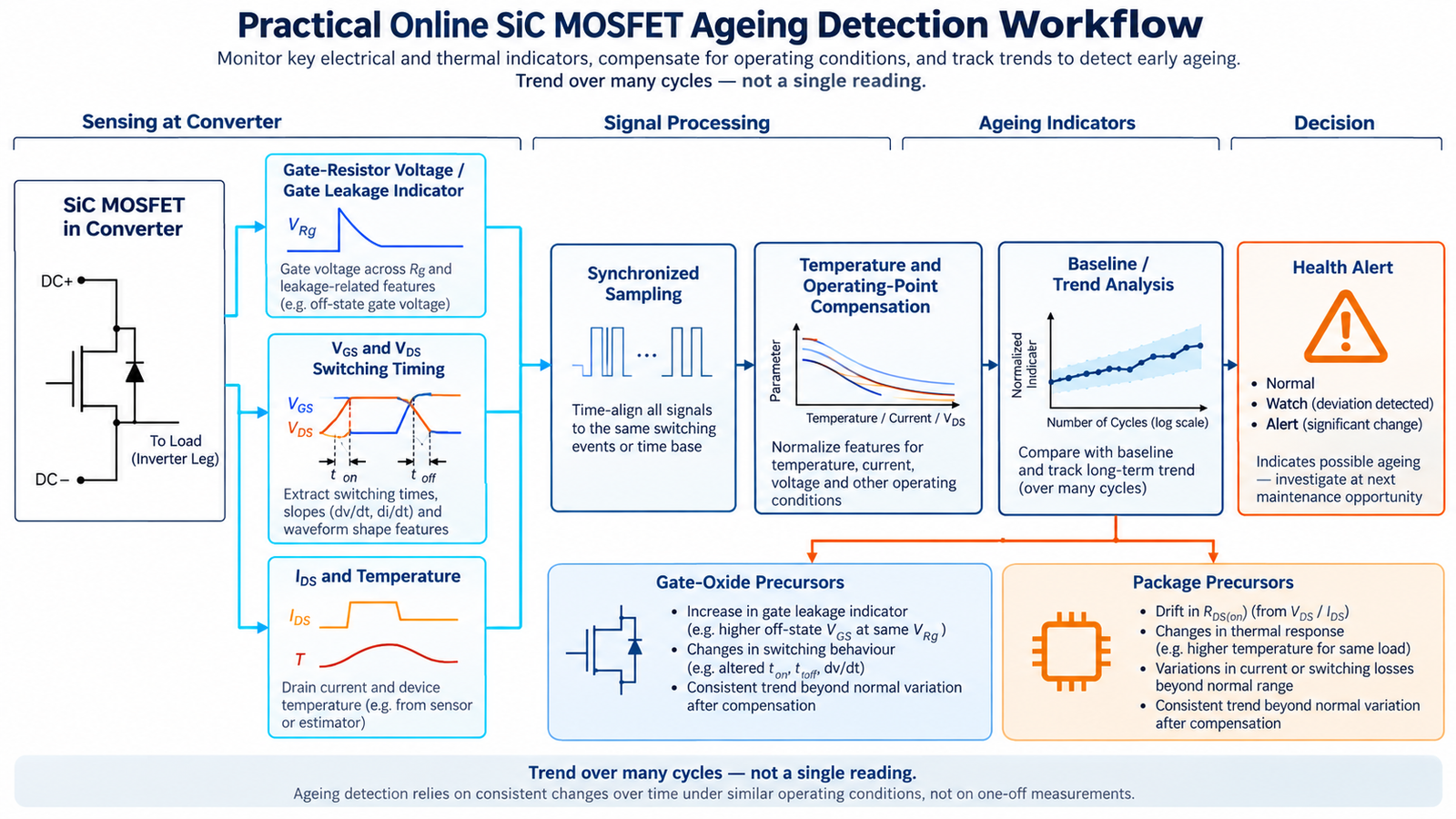
A practical method for online ageing detection in SiC MOSFETs measures an electrical precursor during normal operation, compensates it for temperature and operating point, and tracks its deviation from a healthy baseline. The goal is condition awareness: detect a statistically meaningful trend before degradation becomes a catastrophic open- or short-circuit failure.
The 2017 IEEE APEC paper “A Method for Online Ageing Detection in SiC MOSFETs” by Feyzullah Erturk and Bilal Akin focuses on gate-oxide degradation and uses the voltage associated with gate leakage through the gate path as an online indicator. DOI: 10.1109/APEC.2017.7931211. A deployable monitor should preserve that physical connection while adding synchronization, compensation, diagnostics, and safe alert logic.
Why SiC MOSFET ageing needs online monitoring
SiC MOSFETs switch high voltage and current at fast edge rates and often operate in hot, compact converters. Their efficiency advantages support electric vehicles, charging, solar, industrial drives, and data-center power, but those applications also demand high availability. Periodic offline tests may miss degradation developing between service intervals.
Online monitoring uses measurements already available in the converter or adds isolated sensing around the gate and power stage. It can flag a change while the unit is still operating, allowing controlled derating or planned maintenance. Monitoring does not remove the need for correct gate bias, layout, protection, and thermal design. The guide to negative gate bias for SiC MOSFETs covers one important reliability decision.
Ageing mechanisms are not one single fault
Gate-oxide degradation
Electrical field, temperature, defects, and repetitive stress can change oxide or interface properties. Possible precursors include gate leakage, threshold-voltage shift, transconductance change, and altered switching behavior. A gate-path measurement is most directly related to this degradation family.
Package and interconnect degradation
Power cycling expands and contracts dissimilar materials. Bond wires, clips, die attach, solder, and terminals can fatigue. On-state resistance or voltage may rise, thermal impedance may change, and local temperature may increase. These signals are not unique: temperature and contact resistance can produce similar observations.
External circuit drift
A changed gate resistor, driver supply, connector, current sensor, cooling system, or DC-link condition can imitate device ageing. A useful detector must distinguish the monitored MOSFET from its measurement chain and surrounding circuit.
Core gate-leakage detection concept
Place a known resistance in the gate path and measure a small voltage related to gate current during a carefully selected interval. The original method links an increase in measured gate-resistor voltage to increased gate-source leakage caused by gate-oxide degradation. Because normal switching gate current is much larger than leakage, timing and bandwidth are crucial.
Do not sample arbitrarily during a fast edge. Parasitic inductance, common-mode displacement current, Miller current, driver output impedance, and probe coupling can dominate the signal. A repeatable measurement window may be during a stable gate-bias interval after switching transients have settled, or it may use a deliberately defined diagnostic pulse when system operation allows.
Recommended online monitoring architecture
- Acquire synchronized signals. Measure gate-path voltage and VGS, and record VDS, drain current, driver supply, device or case temperature, and switching state.
- Define a repeatable window. Trigger from the PWM command or measured switching event, reject blanking intervals, and average samples at the same electrical condition.
- Extract health features. Candidates include a gate-leakage proxy, threshold-related timing, Miller-plateau duration, turn-on or turn-off delay, and temperature-normalized on-state resistance.
- Compensate operating conditions. Correct features for temperature, current, DC-link voltage, gate voltage, gate resistance, and switching slew rate.
- Compare with a baseline. Store healthy distributions for operating bins or use a fitted model, then calculate residuals.
- Trend over time. Apply robust averaging or change detection and require persistence before issuing a warning.
- Cross-check sensors. Correlate gate-related and package-related indicators so an external driver or cooling fault is not misclassified.
Signal-conditioning challenges
SiC switching nodes can change by tens of kilovolts per microsecond. Common-mode transient immunity, isolation capacitance, bandwidth, input protection, and PCB geometry directly affect measurement credibility. A long trace or ordinary ground-referenced probe can create a dangerous loop and a false waveform.
Use an isolated or differential front end rated for the actual common-mode voltage and dv/dt. Keep the gate sensing loop small, provide a Kelvin source reference where possible, and characterize channel-to-channel timing skew. The monitor must not add enough capacitance or resistance to change the gate waveform it is trying to observe.
Temperature and operating-point compensation
Threshold voltage, on-resistance, leakage, propagation delay, and switching energy all vary with temperature. Drain current and DC-link voltage also change switching time and the Miller plateau. Without compensation, a hot day or different load may look like accelerated ageing.
A practical baseline can use a multidimensional lookup table indexed by temperature, current, and bus voltage, or a regression model trained from healthy devices. The health residual is measured feature minus expected healthy feature at the same condition. Restrict comparisons to regions where the sensor has adequate signal-to-noise ratio.
Temperature itself may be estimated from a calibrated temperature-sensitive electrical parameter, but self-heating and switching noise complicate the estimate. Direct case or substrate sensing is slower but can provide a valuable independent channel.
Separate gate-oxide and package indicators
A gate-leakage trend or consistent gate-related timing shift supports a gate-oxide hypothesis. A temperature-corrected rise in RDS(on), change in thermal impedance, or imbalance among parallel devices may support an interconnect or package hypothesis. Neither is perfectly unique.
Use a small diagnostic matrix rather than a single threshold. For example, gate-leakage residual high with stable RDS(on) points toward the gate path; RDS(on) and junction-to-case thermal response rising together suggests package degradation; all channels changing after a driver-supply shift suggests an external cause.
Baseline and decision logic
Build a baseline after manufacturing test or commissioning, once the system has stabilized. Record unit-to-unit variation instead of assuming every new device has the same value. Ageing alerts should be based on trend magnitude, slope, persistence, confidence, and cross-sensor agreement.
Three levels are useful: observation for a small persistent deviation, warning for a confirmed trend, and protection or derating for a value associated with unacceptable risk. A single outlier should normally be logged and rejected unless it coincides with a dangerous electrical limit.
Validation plan
- Characterize healthy devices across the complete voltage, current, temperature, and frequency range.
- Measure sensor noise, drift, common-mode error, timing uncertainty, and calibration repeatability.
- Apply controlled accelerated stress that targets a known mechanism without mixing unrelated failures.
- Pause at intervals for offline reference measurements such as gate leakage, threshold voltage, RDS(on), and microscopy when available.
- Demonstrate that the online indicator correlates with the reference measurement across multiple devices.
- Test nuisance conditions: driver replacement, gate-resistor tolerance, cooling degradation, load steps, EMI, and sensor faults.
- Define false-alarm and missed-detection rates before setting field thresholds.
Limits of the method
A gate-path indicator does not detect every SiC failure mechanism and does not directly produce universal remaining useful life. The relationship between a precursor and time to failure depends on stress profile, device design, package, mission history, and threshold definition.
Monitoring electronics can also fail. Safety-critical protection must continue to use independent fast overcurrent, overvoltage, desaturation or short-circuit, undervoltage, and overtemperature functions. Condition monitoring is a slower diagnostic layer, not a replacement for cycle-by-cycle protection.
Design practices that reduce false ageing signals
- Use a Kelvin source connection and compact gate loop.
- Keep gate voltage within the manufacturer’s positive and negative limits.
- Control drain overshoot and false turn-on through layout and calibrated gate resistance.
- Record firmware, driver, sensor, and cooling changes with the health history.
- Compare parallel devices at equivalent current and temperature.
- Preserve raw event snapshots so engineers can audit an alert.
Voltage-class-specific gate-drive requirements also matter. The discussion of 800 V SiC MOSFET gate drive shows why operating conditions must be tied to the exact device family. For application context, see the SiC upgrade path for EV traction systems.
Frequently asked questions
What is the best precursor for SiC MOSFET ageing?
There is no universal best precursor. Gate leakage is physically relevant to gate-oxide degradation, while normalized on-resistance and thermal behavior are more relevant to some package failures. Use the indicator tied to the mechanism of interest.
Can VGS(th) alone predict failure?
No. Threshold voltage varies with temperature, measurement current, device history, and technology. A compensated trend can contribute evidence, but should not be the only diagnostic.
Can the monitor run during normal PWM operation?
Yes, if sensing is isolated, synchronized, nonintrusive, and limited to repeatable operating windows. Some systems may schedule occasional diagnostic pulses to improve signal quality.
Does an ageing alert tell the remaining useful life?
Not by itself. Remaining-life prediction requires a validated degradation model, mission profile, uncertainty bounds, and population data. The online method first provides evidence that a health indicator has changed.