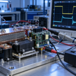
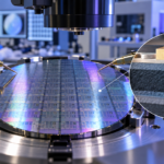
Yes, SiC MOSFETs can be used to power drones, but they make the most sense in high-voltage, high-power propulsion systems rather than small hobby quadcopters. A 400 V or 800 V industrial UAV or eVTOL inverter can benefit from SiC’s low switching loss, high temperature capability, and high-voltage performance. A 6S, 12S, or other low-voltage drone usually gets a better result from low-voltage silicon MOSFETs.
The correct decision is not based on the phrase “wide bandgap.” It is based on total aircraft mass, efficiency at the actual flight cycle, fault tolerance, cost, electromagnetic compatibility, cooling, and certification. SiC is one device option inside the motor inverter; it does not replace the battery, controller, current sensing, gate driver, motor, or propeller design.
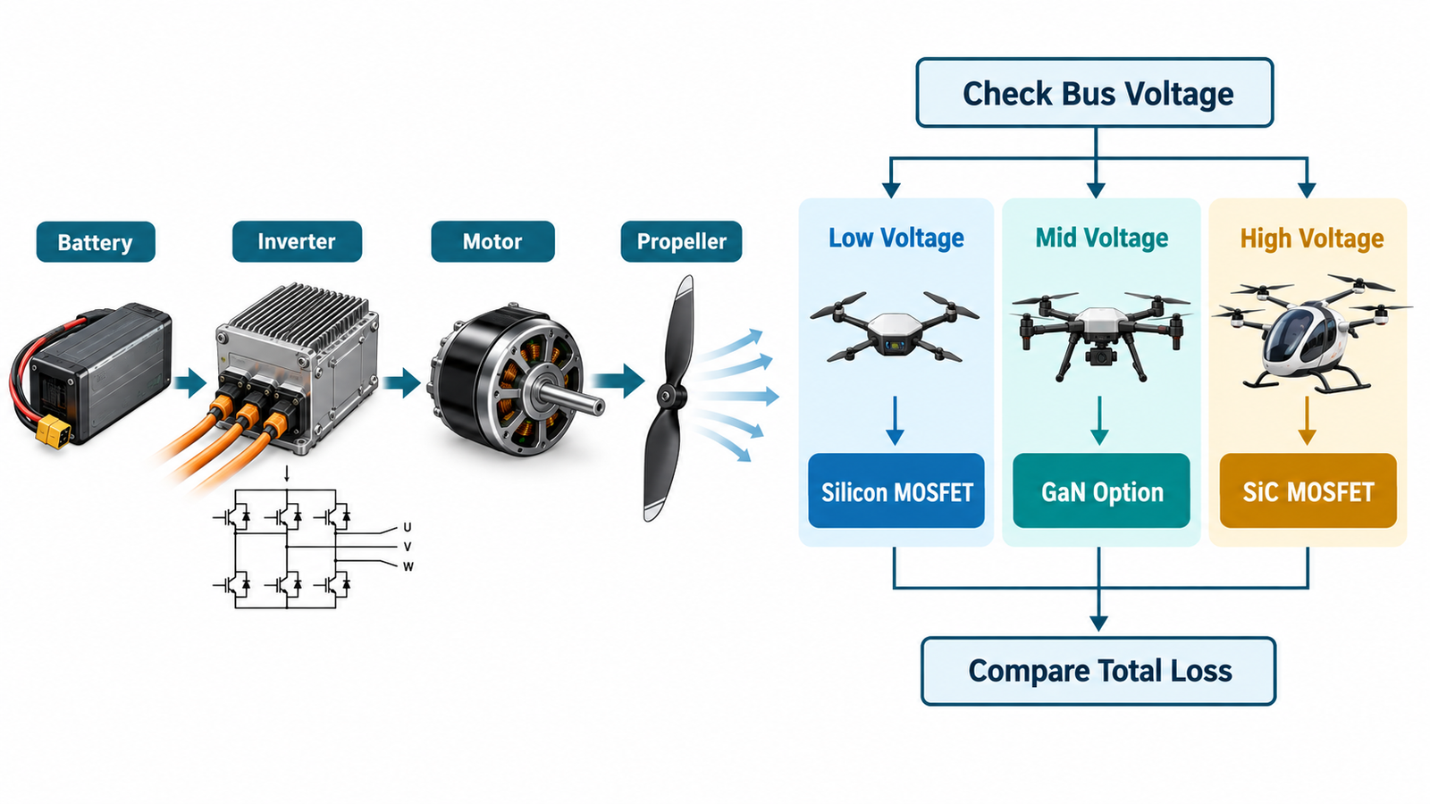
Where SiC fits in a drone powertrain
The battery feeds a three-phase inverter. Six or more power switches commutate current through the motor windings according to the flight controller’s torque command. SiC MOSFETs can occupy the same functional positions as silicon MOSFETs or IGBTs, but their gate-voltage limits, switching speed, short-circuit behavior, body-diode characteristics, and protection needs differ.
In a small multirotor, the bus may be below 100 V and current can be very high. Modern low-voltage silicon MOSFETs offer milliohm or sub-milliohm resistance and inexpensive compact packages. A 650 V or 1200 V SiC MOSFET carries voltage capability that the aircraft never uses and may have higher channel resistance or cost than a purpose-built low-voltage device.
In a large cargo drone or eVTOL aircraft, raising bus voltage reduces current for the same power. Lower current can reduce conductor mass and copper loss, but it increases insulation, clearance, arcing, connector, isolation-monitoring, and service-safety requirements. At these higher voltages, SiC can switch efficiently where a silicon IGBT would lose more energy and where a low-voltage silicon MOSFET cannot block the bus.
Potential advantages of SiC MOSFETs
- Lower high-voltage switching loss: useful when PWM frequency or commutation energy is significant.
- Higher temperature capability: can expand thermal margin, although the package, capacitors, driver, sensors, and insulation still have their own limits.
- Higher switching frequency: may reduce filter, capacitor, or motor magnetic requirements, but only after EMI and motor loss are considered.
- High power density: lower loss and smaller cooling hardware can reduce propulsion-unit volume and mass.
- Efficient regeneration: synchronous control can return energy during deceleration or propeller windmilling when the system architecture supports it.
These advantages are most valuable when the inverter operates at hundreds of volts. Related automotive experience is summarized in the guide to upgrading EV traction systems with SiC MOSFETs and diodes; drone designers face many of the same electrical tradeoffs but with stricter mass and airborne-fault constraints.
Why SiC is not automatically lighter
The transistor may reduce semiconductor and heatsink loss, yet the total system can gain mass from isolated drivers, shielding, common-mode filters, stronger insulation, contactors, precharge components, fault containment, and high-voltage wiring. The motor may also experience greater bearing current or insulation stress from faster edges. Weight savings must be demonstrated at aircraft level.
Conduction loss is approximately current squared times on-resistance during the on interval. Switching loss depends on voltage, current, transition energy, and frequency. Calculate both across hover, climb, cruise, descent, and emergency operation. A device that wins at maximum power may not win during long cruise or partial load.
Gate drive and layout
Use a gate driver specified for the selected SiC MOSFET, not a generic silicon driver by assumption. Confirm recommended positive gate voltage, allowed negative voltage, Miller immunity, source and sink current, propagation delay, isolation rating, and undervoltage lockout. A Kelvin source connection prevents power-source inductance from corrupting gate voltage.
The DC-link capacitor and phase-leg devices should form a compact commutation loop. Stray inductance creates overshoot and ringing that consume voltage margin and radiate noise into navigation, radio, GNSS, sensor, and flight-control electronics. Gate resistance can slow the edge, but the first remedy is physical layout. The article on negative gate bias for SiC MOSFETs explains when a negative off voltage may help and when it introduces risk.
Thermal design in flight
Cooling changes with air density, altitude, forward speed, rotor wash, enclosure position, and contamination. A bench fan does not duplicate the mission. Build a loss map, model junction-to-coolant or junction-to-air paths, and measure case temperature and coolant conditions during representative profiles. Review how to calculate MOSFET heat-sink size, then adapt the method to transient flight segments.
SiC devices can survive high junction temperature, but designing continuously near the absolute maximum shortens margin for blocked airflow, hot-soak restart, component tolerance, and aging. Capacitors and interconnects may set a lower temperature ceiling than the die.
Protection and airworthiness
Short-circuit withstand time for a SiC MOSFET can be brief. Protection should detect desaturation or overcurrent, turn the device off without destructive voltage overshoot, and report the fault to the flight-control system. Each phase leg also needs DC-bus overvoltage control, gate-supply monitoring, temperature sensing, and defined behavior after sensor or communication failure.
Single-point fault analysis matters because a shorted switch can apply braking torque or uncontrolled current to a motor. Redundant propulsion channels, contactors, fuses, DC-bus segmentation, and software response must be coordinated. Do not treat a semiconductor’s reliability qualification as evidence that the complete propulsion system is flight safe.
How to decide
- Define bus voltage, continuous and peak power, current ripple, PWM frequency, motor inductance, altitude, cooling, and flight profile.
- Shortlist silicon, GaN, and SiC devices with adequate transient voltage margin.
- Model conduction, switching, diode, gate-drive, capacitor, busbar, and motor losses at several operating points.
- Include the mass of cooling, filters, insulation, drivers, shielding, and protection.
- Prototype one phase leg and measure efficiency, overshoot, common-mode current, EMI, and temperature.
- Validate abnormal conditions, vibration, humidity, altitude, thermal cycling, and lifetime before flight qualification.
For compact power electronics, the PCB thermal-path guide for power MOSFETs provides a useful starting point, but high-power aircraft modules normally need busbars, insulated substrates, or liquid cooling as well.
Frequently asked questions
Can I replace the MOSFETs in a hobby ESC with SiC parts?
Usually not as a drop-in change. The voltage class, package, pinout, gate voltage, capacitance, dead time, protection, and PCB layout differ. For a low-voltage ESC, good silicon MOSFETs are normally more appropriate.
Is GaN better than SiC for drones?
Neither is universally better. GaN is attractive at lower or medium voltages and very high frequency; SiC is especially strong at high voltage and high power. Compare complete inverter performance.
Does SiC improve flight time?
It can if propulsion-inverter losses are a meaningful part of the energy budget and the saved cooling or wiring mass exceeds any added system mass. The improvement must be measured over the actual mission.