The safest way to identify a Schottky diode is to read its complete marking, match the code and package to a manufacturer data sheet, and confirm that the pinout and circuit role agree. A stripe usually indicates cathode polarity, but ordinary p-n rectifiers use the same convention. A low forward-voltage reading supports Schottky identification but is not conclusive by itself.
Identification matters because superficially similar diodes can differ by hundreds of volts, orders of magnitude in leakage, package pinout, surge capability, and switching behavior. Guessing can create an unsafe or unreliable repair.
Start with the complete printed code
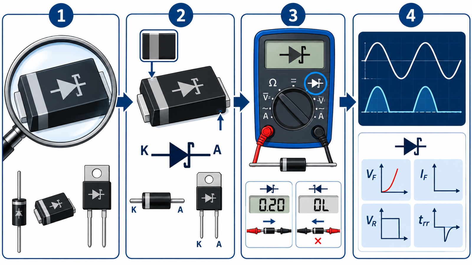
Clean the package gently and inspect it under angled light or magnification. Record every letter, number, logo, line, dot, and band before removing the part. Search an official manufacturer marking guide or product data sheet using both the code and package style. Short SMD top marks are not globally unique, so a code alone can match several unrelated devices.
Include package dimensions, pin count, manufacturer logo, PCB reference designator, and equipment model in the search. If the result claims a single diode but the board footprint and schematic require a common-cathode dual device, the match is wrong.
Separate polarity marks from technology clues
On many two-terminal parts, a band marks the cathode. It tells you how the diode is oriented, not whether it uses a Schottky metal-semiconductor junction. Likewise, the schematic diode symbol may have a stylized cathode mark, but symbol libraries and simplified service drawings are inconsistent.
Learn the operating distinction in what a Schottky diode is, then use actual specifications rather than artwork as proof.
Use circuit position as supporting evidence
Schottky diodes commonly appear as low-voltage output rectifiers, buck-converter catch diodes, reverse-polarity protectors, power OR-ing elements, RF detectors, clamps, and fast signal paths. A low-voltage high-current diode next to an inductor and switching node is a strong candidate. A high-voltage mains rectifier is more likely silicon p-n or SiC, though exceptions exist.
Trace the net names and nearby controller data sheet. Note the maximum voltage the diode must block, expected current direction, frequency, and package thermal path. Circuit context narrows the candidate list but should never override a readable part number.
Check the forward junction
Remove power, discharge capacitors, and use diode mode. A Schottky device often reads around 0.15 to 0.45 V at a multimeter’s small test current, compared with roughly 0.5 to 0.8 V for many silicon p-n diodes. These ranges overlap. Temperature, device area, test current, and in-circuit paths can shift the result.
Lift one lead when necessary and test every junction in a multi-diode package. Follow the safe procedure in how to check a Schottky diode. A meter test can identify polarity and obvious faults, but not the guaranteed voltage or current rating.
Compare reverse leakage and capacitance carefully
Schottky diodes often have higher reverse leakage than p-n rectifiers, especially when hot, and their junction capacitance can be significant. Controlled leakage or capacitance measurements may support identification when documentation is unavailable, but they require safe, current-limited fixtures and comparison with known devices.
Never raise reverse voltage simply to see where an unknown diode breaks down. Exceeding its rating can permanently damage it or create a shock hazard. Use a data sheet or replace the whole assembly when the required rating cannot be established.
Confirm the replacement specification
Once a likely identity is found, verify repetitive peak reverse voltage, average and RMS current, surge current, forward voltage at actual current, reverse leakage at hot temperature, capacitance, package, polarity, qualification, and thermal resistance. Match the exact suffix because it can encode package, voltage, or reel options.
Use Schottky application tradeoffs and rectifier selection fundamentals to decide whether the original technology is still appropriate.
Engineering checklist
Photograph the device in place, record orientation, and preserve the removed part. Check official service information, schematic, bill of materials, and controller reference design before trusting reseller listings. If several candidates share a top mark, compare package dimensions and every electrical requirement. Reject any candidate that cannot withstand the circuit’s worst-case reverse voltage, current pulses, and temperature.
Create a short identification record with board location, observed top mark, package measurements, probable maker, candidate links, measured polarity, and reasons for accepting or rejecting each candidate. This prevents a later technician from repeating the same uncertain search. If the equipment is safety critical or connected to mains, escalate an unresolved identity to the manufacturer rather than fitting an approximate substitute.
After replacement, start with current limiting and monitor output waveform, reverse voltage, forward drop, and case temperature. Validate high line, full load, load release, startup, and hot operation. If the original part failed, investigate cooling, capacitors, inductors, switch timing, snubbers, and downstream shorts. Identification solves only the component name; it does not explain the root cause.
Frequently asked questions
Does a silver band mean the diode is Schottky?
No. The band usually marks cathode polarity and is common on many diode technologies.
Can a multimeter prove a diode is Schottky?
It can show a relatively low forward drop, but overlapping device behavior and test conditions mean the result is supporting, not definitive, evidence.
What if the SMD code matches several parts?
Use the logo, package dimensions, pinout, circuit role, board designator, and required ratings to narrow it; do not guess if safety depends on the answer.
Are all low-voltage rectifiers Schottky diodes?
No. Ultrafast p-n diodes, synchronous MOSFETs, and other technologies can serve similar roles.