A standard full-wave bridge rectifier uses four diodes. A center-tapped full-wave rectifier uses two diodes and a center-tapped transformer secondary. Both topologies steer current through the load in the same direction during positive and negative input half-cycles, so the output ripple occurs at twice the AC line frequency before filtering.
The correct answer therefore depends on topology. If someone simply says “full-wave rectifier,” ask whether they mean the four-diode bridge or the two-diode center-tapped circuit.

Four diodes in a bridge rectifier
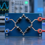
The bridge connects four diodes in a diamond. During one AC half-cycle, one diagonal pair conducts. During the opposite half-cycle, the other pair conducts. The pair selection reverses which AC terminal supplies current, yet the current through the DC load keeps the same polarity. No center tap is required.
For a direct walkthrough, see how many diodes a bridge rectifier uses. At any instant under normal load, two of the four diodes carry the rectified current.
Two diodes with a center-tapped transformer
A center-tapped secondary is effectively two equal windings in series with a midpoint connection. One diode conducts when the upper end is positive relative to the center tap; the other conducts when the lower end is positive. The load current returns through the center tap and maintains one direction.
Only one diode lies in the active load path, reducing forward drop. However, each half-cycle uses only half of the secondary, and the nonconducting diode may see a larger peak inverse voltage. Transformer construction and copper utilization differ from a bridge.
Why both are called full-wave
Half-wave rectification discards one polarity of the AC waveform, producing one output pulse per input cycle. A full-wave circuit flips or redirects the negative half-cycle, producing two pulses per cycle. On 50 Hz mains the unfiltered full-wave ripple is 100 Hz; on 60 Hz mains it is 120 Hz.
The fundamentals in what a rectifier diode is explain forward conduction, reverse blocking, and how a capacitor smooths the pulsed output.
Compare forward drop and transformer use
A bridge current path contains two diode forward drops. At low output voltage, that loss can be significant. A center-tapped path contains one diode drop, but the transformer needs twice-ended secondary construction around a midpoint, and each half-winding conducts alternately. For the same output conditions, voltage and current ratings must be derived carefully.
At high current or low voltage, Schottky diodes or synchronous MOSFET rectifiers may improve efficiency. Their leakage, reverse voltage, drive, timing, and cost introduce other tradeoffs.
Select voltage and current ratings
Calculate repetitive reverse voltage for the chosen topology, including transformer regulation, high-line input, capacitor voltage, leakage spikes, and tolerances. Determine average, RMS, and peak diode current. A reservoir capacitor draws narrow charging pulses, so diode and transformer RMS current can be far above the DC load current. Check nonrepetitive surge for startup.
Use maximum forward drop and thermal resistance at the actual current and temperature. The comparison with Schottky diodes is useful when low voltage drop matters.
Filtering and load behavior
A smoothing capacitor charges near each rectified peak and supplies the load between peaks. Larger capacitance reduces ripple but increases charging-current pulses, inrush, diode stress, transformer heating, and power-factor distortion. Add bleeders, inrush control, fusing, and regulation as the application requires.
A rectifier converts polarity; it does not by itself create a regulated DC supply. Output depends on transformer ratio, input line, load, diode drop, capacitor, and downstream regulation.
Build and verify safely
Check diode orientation before applying power. Begin with a current-limited isolated source appropriate to the voltage class. Measure DC polarity, output ripple, individual diode temperature, transformer temperature, startup current, and reverse-voltage stress. Keep oscilloscope grounding safe; mains-connected bridges are not automatically isolated.
Part type matters as much as orientation; the discussion of whether a Zener can serve as a rectifier explains why current, surge, reverse-voltage, recovery, and thermal ratings must match the job. Use certified components and spacing for mains designs.
A simple design example
Suppose an isolated transformer secondary supplies a capacitor-input DC load. With a bridge, connect the two secondary leads to the AC terminals and take DC from the marked positive and negative terminals. Current crosses two diode junctions on every charging pulse. With a center-tapped secondary, connect the tap to one load rail and the two end leads through separate diodes to the other rail. Only one junction conducts, but each half-winding works on alternate half-cycles.
Do not compare the circuits using transformer RMS voltage alone. Define whether the value is end-to-end or half-winding, then calculate peak voltage, diode drop, load sag, ripple, peak inverse voltage, winding RMS current, and copper use. Add high-line and no-load transformer regulation. This exercise explains why the two-diode circuit is not automatically smaller or more efficient even though it contains fewer rectifiers. The transformer and complete loss budget decide.
Frequently asked questions
Does full-wave always mean four diodes?
No. The common bridge uses four; a center-tapped transformer circuit uses two. Both use both halves of the AC waveform.
How many bridge diodes conduct at once?
Two conduct in series on each half-cycle, while the other two block.
Why use a two-diode full-wave rectifier?
It has one diode drop in the conducting path, but requires a center-tapped transformer and imposes different winding and reverse-voltage requirements.
Can one diode make a full-wave rectifier?
Not in the ordinary passive single-phase circuits described here. One diode produces half-wave rectification.