Attach a heatsink to a MOSFET by creating a flat, clean, thin thermal path and applying controlled mounting pressure without violating electrical isolation. For tabbed packages such as TO-220 or TO-247, the metal tab is often connected to the drain. Directly bolting it to a conductive heatsink can place the entire heatsink at a dangerous switching voltage.
Before choosing hardware, read the device and package documentation. Determine the heat-flow surface, tab connection, required insulation voltage, recommended torque or clip force, thermal-interface material, clearance, and maximum junction temperature.
Calculate the thermal path first
The junction temperature estimate follows power loss through junction-to-case, case-to-sink, and sink-to-ambient thermal resistance. An insulator and interface material add case-to-sink resistance. If the allowable heatsink resistance is unrealistic, change the MOSFET, package, switching loss, airflow, or mechanical design rather than treating attachment as a cure.
The process in calculating MOSFET heatsink size turns power and temperature limits into a usable thermal target.
Decide whether electrical insulation is required
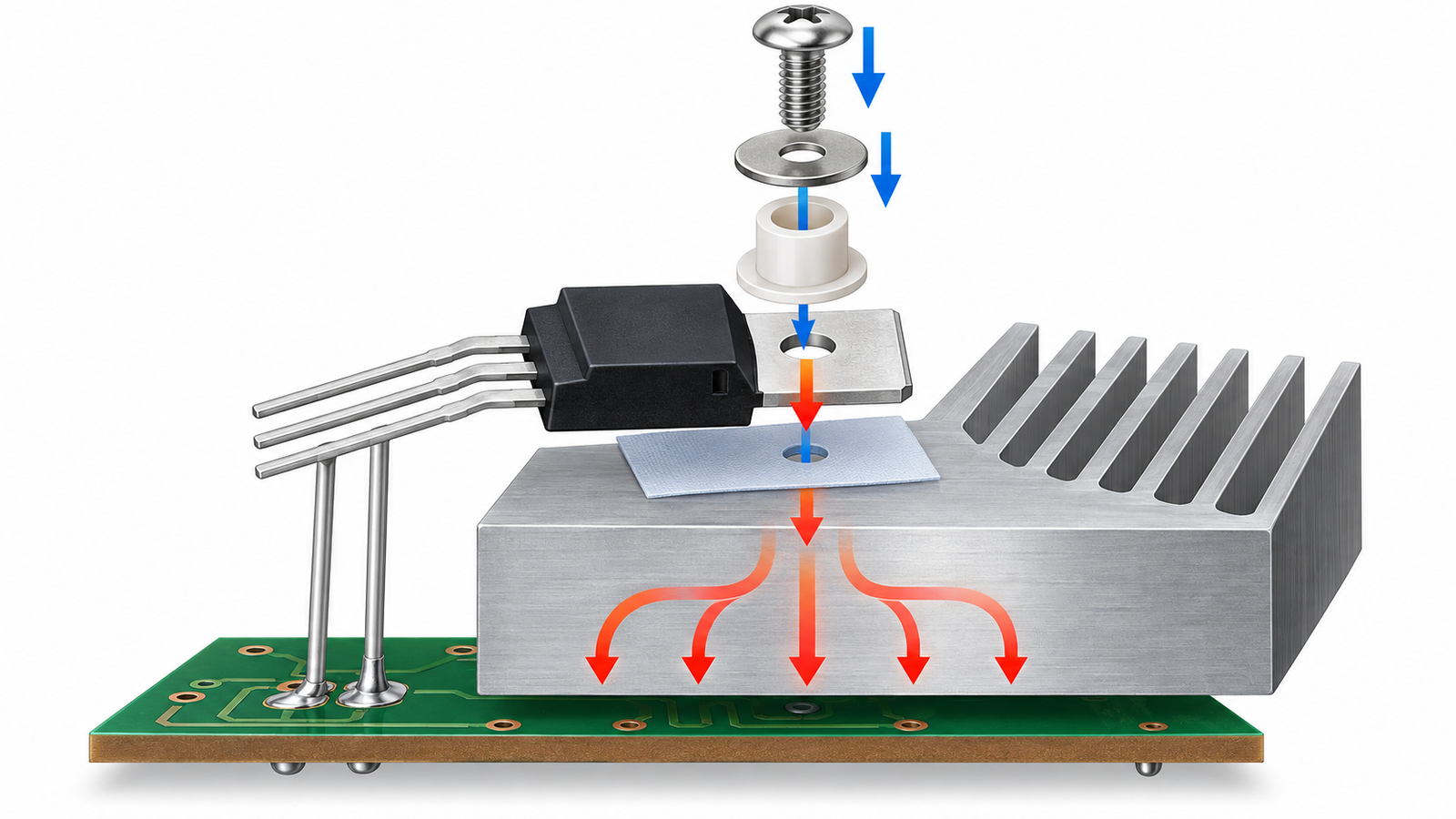
Check the package drawing. A bare metal tab is commonly tied to drain, while a fully insulated package provides molded isolation with higher thermal resistance. If multiple devices share a sink, their tabs may sit at different switching potentials. Use rated pads, mica with approved compound, ceramic isolators, or an isolated package as appropriate.
Insulation must withstand working voltage, transients, pollution, temperature, mounting pressure, and aging. A plastic shoulder washer may be required so the screw does not electrically bridge the tab to the heatsink.
Prepare the mating surfaces
Disconnect and discharge the equipment. Remove burrs around drilled holes and verify that the heatsink is flat where the package will sit. Clean grease, dust, metal particles, and old pad residue using a compatible method. Inspect the MOSFET tab and insulator for scratches, cracks, folds, or embedded debris.
Dry fit the assembly. Leads should enter the PCB without pulling the package away from the sink, and the heatsink should not force the board to bow. Plan creepage and airflow before soldering rigidly.
Apply the interface material correctly
Thermal compound fills microscopic voids; it is not a thick adhesive layer. Apply only enough to wet the surfaces according to the material supplier. A preformed silicone pad or phase-change film should sit flat without wrinkles and should not be reused unless its documentation explicitly allows it. Mica normally needs a thin approved compound on both sides.
Thicker is not automatically safer or cooler. Extra interface thickness increases thermal resistance, while too little insulation may fail electrically. Follow the specified stack rather than improvising with household tape or general-purpose glue.
Use controlled mounting force
Install the correct screw, washer, shoulder washer, spring element, or clip. Tighten to the package manufacturer’s specified torque with a calibrated tool when torque is given. A spring clip can maintain pressure across temperature cycles and place force near the die area. Keep the package seated while tightening.
Under-tightening leaves air gaps. Overtightening can bow the tab, lift part of the contact area, crack a ceramic washer, damage molding, or stress the die and PCB. Mechanical damage can raise thermal resistance even when the assembly looks tight.
Verify electrical and thermal performance
Before energizing, inspect alignment and measure resistance between the tab or drain and heatsink when isolation is required. Perform the specified dielectric test using appropriate equipment and safety controls; an ohmmeter alone does not prove high-voltage insulation. Confirm that the sink cannot be touched if it is intentionally live.
Apply load gradually and measure case or tab-adjacent temperature after stabilization. Estimate junction temperature from loss and thermal resistance. The overview of how heatsinks cool MOSFETs explains why case temperature, airflow, and junction temperature are different quantities.
Practical design review
Release a mechanical drawing that defines the package, insulator, interface material, fastener, washer, clip, torque or force, heatsink finish, and assembly order. Include minimum creepage and clearance, prohibited burrs, cleanliness, and whether compound is permitted. If a top-side-cooled surface presses against a cold plate, control gap and coplanarity and add board support so clamping does not bend the PCB.
For several MOSFETs, check combined heat flow and tab voltages. The guide to sharing a heatsink between MOSFETs covers isolation and thermal interaction. Validate minimum and maximum interface thickness, fastener tolerance, vibration, thermal cycling, fan failure, dust, and high ambient. Record the exact temperature measurement points and preserve margin below the device limit.
Inspect sample assemblies after thermal cycling. Look for pad extrusion, dried compound, relaxed fasteners, board bow, cracked washers, fretting, and discoloration. If the heatsink is user-accessible, verify touch temperature and protective bonding or insulation requirements in addition to semiconductor temperature.
Frequently asked questions
Can I bolt a MOSFET directly to an aluminum heatsink?
Only if electrical connection of the tab to that heatsink is acceptable and safe. Many MOSFET tabs are connected to drain, so an insulator is often required.
Do I always need thermal paste?
No. Some pads and phase-change materials are designed for dry installation. Use the interface system and thickness specified for the package and insulation requirement.
How tight should the screw be?
Use the package or module manufacturer’s specified torque. There is no universal value, and excessive torque can worsen contact or damage the device.
Can I glue a heatsink to a MOSFET?
Only with a characterized thermally conductive, electrically appropriate adhesive in a design intended for it. Adhesive complicates rework and must tolerate temperature and stress.