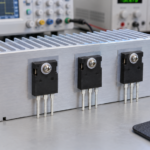
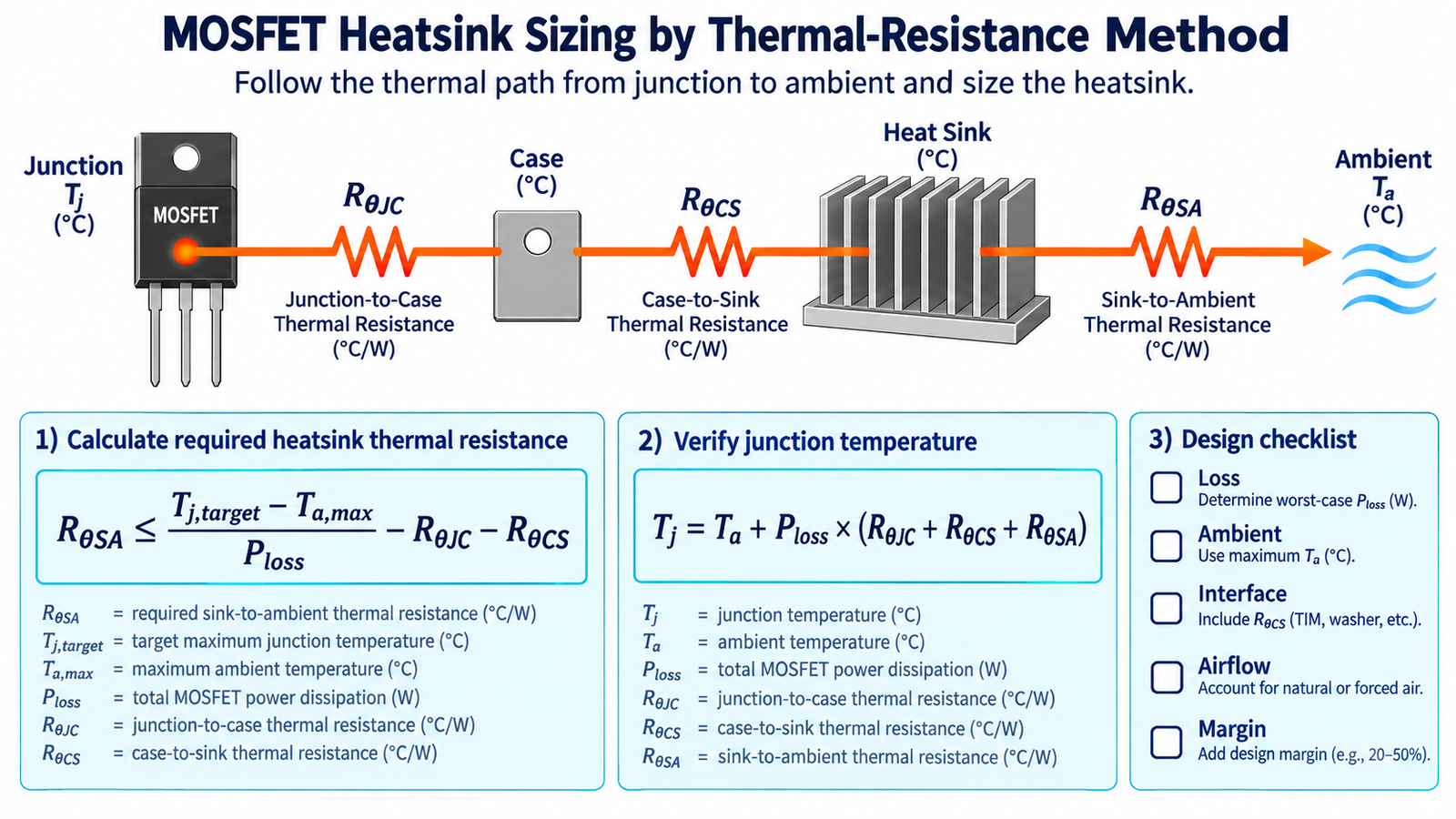
To calculate heat sink size for a MOSFET, convert the allowable temperature rise into a required sink-to-ambient thermal resistance. For one device on one heatsink, a useful steady-state equation is RθSA ≤ (Tj,target − Ta,max) / Ploss − RθJC − RθCS. Select a heatsink whose rated RθSA is equal to or lower than the calculated value, add design margin, and verify the finished assembly.
“Size” therefore means thermal performance in degrees Celsius per watt, not only physical dimensions. Two heatsinks of similar volume can perform differently because fin geometry, orientation, surface finish, airflow, and enclosure recirculation affect convection. The same principle is part of the broader MOSFET thermal-path design process.
Step 1: Calculate MOSFET power loss
The heatsink calculation is only as good as the loss estimate. Add conduction, switching, diode, output-capacitance, gate-related, and any linear-mode losses that occur in the intended circuit.
For a fully enhanced switching MOSFET, approximate conduction loss with Pcond = Irms² × RDS(on,hot). Use RMS current, the applicable duty cycle, and on-resistance at the expected junction temperature. A first switching estimate is Psw ≈ 0.5 × VDS × ID × (tr + tf) × fsw, but measured switching energy or manufacturer loss models are better when capacitance, reverse recovery, and nonlinear transitions are important.
If a MOSFET operates in linear mode, a simple resistance calculation is insufficient. Voltage and current coexist across the device, and the relevant pulse or DC point must remain inside the MOSFET safe operating area.
Step 2: Choose maximum ambient and target junction temperatures
Ta,max is the air temperature actually seen by the heatsink, not necessarily room temperature. In an enclosure, it may be much hotter because other components preheat the air. Measure near the heatsink inlet after the system reaches thermal equilibrium.
Tj,target should be below the datasheet absolute maximum junction temperature. The difference provides margin for component tolerance, dust, fan ageing, interface variation, load uncertainty, and inaccurate loss estimates. A device rated to 150 °C or 175 °C should not automatically be designed to operate continuously at that limit.
Step 3: Build the thermal resistance chain
For a MOSFET mounted to a heatsink, the main steady-state path is:
Tj = Ta + Ploss × (RθJC + RθCS + RθSA)
- RθJC: junction-to-case resistance from the datasheet for the relevant package surface.
- RθCS: case-to-sink resistance of the thermal pad, grease, insulator, and mounting interface.
- RθSA: heatsink-to-ambient resistance under the specified orientation and airflow.
Do not substitute junction-to-ambient resistance for junction-to-case resistance in this chain. RθJA describes a complete standardized board or ambient path. It may be useful for a package cooled through the PCB, but combining it with a separate heatsink chain double-counts paths.
Step 4: Solve for the required heatsink
Rearranging the thermal equation gives:
RθSA ≤ (Tj,target − Ta,max) / Ploss − RθJC − RθCS
Lower RθSA means better cooling and usually a larger heatsink, more airflow, or both. If the result is zero or negative, even an ideal heatsink cannot meet the target with the stated junction-to-case and interface resistances. Reduce semiconductor loss, choose a lower-resistance package, lower ambient temperature, use liquid or forced-air cooling, or share loss across more devices.
Worked MOSFET heatsink example
Assume the MOSFET dissipates 8 W at worst case, maximum local ambient is 50 °C, target junction temperature is 125 °C, RθJC is 1.2 °C/W, and RθCS is 0.5 °C/W.
RθSA ≤ (125 − 50) / 8 − 1.2 − 0.5 = 7.675 °C/W.
A catalog heatsink rated at 7 °C/W or better appears suitable for this first pass. Its predicted junction temperature is 50 + 8 × (1.2 + 0.5 + 7) = 119.6 °C. That leaves only 5.4 °C below the chosen target, so a designer may choose a still lower RθSA after accounting for tolerance, airflow restriction, and nearby heat sources.
Natural convection versus forced air
A natural-convection rating normally assumes a stated orientation in open air. Vertical fins often perform better because warm air can rise through the channels. A horizontal board, sealed enclosure, cable obstruction, or closely spaced wall can reduce performance.
Forced-air ratings depend on air velocity through the fins, not simply the fan’s unrestricted flow rating. Filters, vents, back pressure, and recirculation alter velocity. Check the heatsink curve at the real airflow and evaluate a stalled-fan condition if failure could create a hazard.
Multiple MOSFETs on one heatsink
When several devices share a sink, the sink-to-ambient rise is based approximately on total heat: Ts − Ta = Ptotal × RθSA. Each device then has its own junction rise above the local sink: Tj,i = Ts,local + Pi × (RθJC,i + RθCS,i). Heat spreading makes the sink temperature nonuniform, especially when devices are clustered.
Electrical isolation pads can increase RθCS. Metal tabs may be connected to the drain, so insulation and creepage requirements must be checked before assuming a bare metal-to-metal interface. Mounting torque, flatness, clip pressure, and grease thickness also affect contact resistance.
Transient loads and thermal impedance
Steady-state thermal resistance is conservative for short pulses because the package and heatsink store heat. For pulsed loads, use the datasheet transient thermal impedance ZθJC(t) and the pulse duty pattern. Repetitive pulses can accumulate heat, so calculate the full periodic waveform or simulate an RC thermal network rather than treating every pulse as isolated.
Thermal capacitance does not protect a device from electrical overstress. Current, avalanche, and safe operating area must remain valid during every pulse. Switching loss can also rise as the junction warms, producing an iterative electrothermal problem.
How to improve the result before enlarging the heatsink
- Reduce conduction loss. Select lower hot RDS(on), improve current sharing, or use a lower-loss topology.
- Reduce switching loss. Improve gate drive and layout while controlling overshoot and EMI. The gate-resistor tuning guide explains the trade-off.
- Improve the interface. Use the thinnest suitable insulation and thermal material consistent with safety and mechanical tolerances.
- Spread heat. Increase copper, add thermal vias, distribute devices, or use a heat spreader.
- Improve airflow. Remove recirculation, align fins, enlarge vents, or use a controlled fan.
Validate the assembled system
Run the maximum continuous load at maximum input stress and ambient temperature until temperatures stabilize. Measure case or tab temperature with a calibrated thermocouple, resistance method, or carefully prepared infrared target. Estimate junction temperature by adding the measured or calculated junction-to-case rise.
Also test startup, overload, short transients, blocked vents, minimum and maximum line, and fan faults. The article why MOSFETs get hot provides a checklist for separating thermal symptoms from gate-drive or layout problems.
Frequently asked questions
What does a 5 °C/W heatsink mean?
Under its specified test conditions, the heatsink surface rises about 5 °C above ambient for every watt transferred to it. Ten watts would produce an idealized 50 °C rise. Interface and junction-to-case rises must still be added.
Can I use RθJA to select a heatsink?
Usually not directly. RθJA includes the complete device-to-ambient path under a defined board condition. For a case-mounted sink, use RθJC, RθCS, and RθSA. For surface-mount cooling, use the manufacturer’s board data or a validated thermal model.
Is a larger heatsink always better?
Thermally, a lower RθSA usually helps, but size, mass, cost, electrical isolation, airflow, and mechanical stress matter. Beyond a point, reducing device loss or improving airflow is more effective.
Should I use the MOSFET maximum junction temperature?
No. Treat it as an absolute limit. Choose a lower design target with margin appropriate to reliability, mission profile, tolerance, and fault response.